A robot joint driver

A technology of robot joints and drivers, applied in the field of robots, can solve the problems of large space occupation, difficult precise control, complex structure, etc., and achieve the effects of protecting cleanliness, facilitating precise control, and small size

Active Publication Date: 2020-06-16
BEIJING MECHANICAL EQUIP INST
View PDF3 Cites 0 Cited by
  • Summary
  • Abstract
  • Description
  • Claims
  • Application Information

AI Technical Summary

Problems solved by technology

[0003] The purpose of the present invention is to provide a robot joint driver, which solves the problems that the existing hydraulic joint driver takes up a large space, has a complex structure, and is difficult to achieve precise control

Method used


Image

  • A robot joint driver
  • A robot joint driver
  • A robot joint driver

Examples


Embodiment Construction

[0043] The present invention will be further described in detail below in conjunction with the accompanying drawings and specific embodiments.

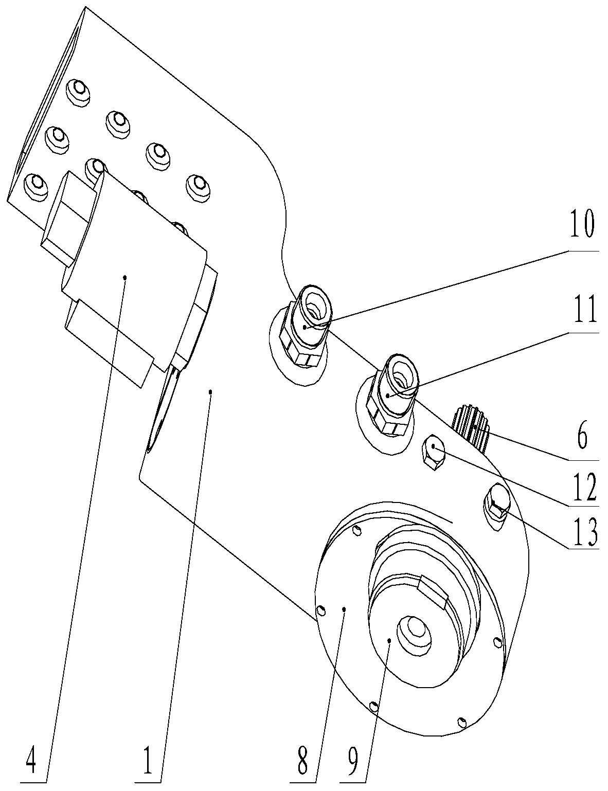
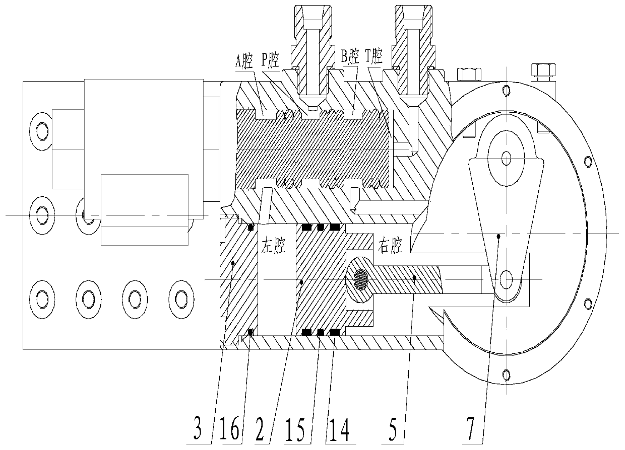
[0044] The invention provides a robot joint driver, such as figure 1 and 2 As shown, it includes housing 1, piston 2, screw plug 3, three-position four-way valve 4, connecting rod 5, rotating shaft 6, crank 7, cover plate 8, encoder 9, pipe joint A10, pipe joint B11, and adjustment screw A12, adjusting screw B13, wear ring 14, lattice ring 15, O-ring 16.

[0045] The three-position four-way valve 4 controls the hydraulic oil to drive the piston 2 to reciprocate, and the piston 2 drives the rotating shaft 6 to rotate through the connecting rod 5 and the crank 7, and the rotating shaft 6 is connected with the corresponding driving parts of the robot.

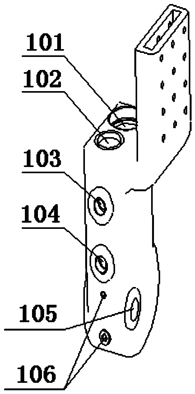
[0046] Such as image 3 As shown, the housing 1 includes a first section with a piston mounting hole 101, a valve hole 102, a P port 103, a T port 104, a rotating shaft mounting hole 1...


PUM


Abstract

The invention provides a robot joint driver. The robot joint driver comprises a shell (1), a piston (2), a connecting rod (5), a rotating shaft (6) and a crank (7), wherein the piston (2) is sealed ina piston mounting hole (101) of the shell (1); the rotating shaft (6) is mounted in a rotating shaft mounting hole (105) of the shell (1); the connecting rod (5) and the crank (7) are located in theshell (1), and the piston (2) is driven to move to and fro through hydraulic oil; and the piston (2) drives the rotating shaft (6) to rotate through the connecting rod (5) and the crank (7). The driver adopting hydraulic driving has the advantages that as an oil cylinder shell, an oil path channel and a joint bearing mechanism are integrated together, the size is small, output torque is large, thestructure is simple and compact, and installation and use are convenient; the rotating angle of a joint is fed back by an encoder, so that accurate control is facilitated; and the rotating angle range of the joint can be adjusted by a regulating screw, so that the application range is wide, and the use is safe and reliable.

Description

technical field [0001] The invention relates to the field of robots, in particular to a robot joint driver. Background technique [0002] There are basically three types of bionic robot joint drive methods: motor drive, pneumatic drive and hydraulic drive. Compared with the motor drive mode, the overall power density is low, the volume is large, and the drive force of the pneumatic drive is small, low rigidity, and it is difficult to achieve precise drive control. The disadvantage is that the power density of the hydraulic drive machine is high, it is easy to realize precise automatic control, and it is more suitable for the drive of high-torque joints. There are two main forms of hydraulic joint drive, one is to use the triangle structure to convert the telescopic motion of the hydraulic cylinder into the rotation output of the joint, and the other is to use the swing cylinder to directly output the joint rotation. Both forms have certain defects. The structural joint driv...

Claims


Application Information

Patent Timeline
Patent Type & Authority Patents(China)
IPC IPC(8): B25J17/02
CPCB25J17/0258
Inventor 贾正伟张利剑胡源渊廖平平高润鹏
Owner BEIJING MECHANICAL EQUIP INST
Why Eureka
Try Eureka