
A hollow hook bending machine

A bending machine and hook technology, used in household appliances, other household appliances, applications, etc., can solve the problems of hollow hook deformation, hard points, low strength, etc., and achieve convenient installation and maintenance, easy cutting, and qualified high rate effect

Active Publication Date: 2019-03-22
重庆针尖内燃机部件制造有限公司
View PDF7 Cites 0 Cited by
  • Summary
  • Abstract
  • Description
  • Claims
  • Application Information

AI Technical Summary

Problems solved by technology

The hook is divided into hollow hook and solid hook. After the solid hook is bent, it can be cut directly by the vertical cutting knife on the bending machine. After the hollow hook is bent, because the hollow hook It has a central hole, so the strength is low. If the vertical cutting knife is used to cut directly after bending, it will cause deformation of the hollow hook and cause the entire hollow hook to be scrapped.
In addition, when the solid hook is bent by the bending machine, it will not be deformed due to its strong strength, and when the hollow hook is bent, because the hollow hook is provided with a central hole, so The strength of the hollow hook is greatly reduced, and it is easy to deform or produce hard points during bending. At present, the forming blocks on the mandrel fixed in the bending machine head generally include four forming blocks evenly arranged. After entering the mandrel, the middle part of the hollow hook will not be tightly hugged by the forming block, which also makes the unclamped part deform when the hollow hook is bent

Method used


Image

  • A hollow hook bending machine
  • A hollow hook bending machine
  • A hollow hook bending machine

Examples


Embodiment Construction

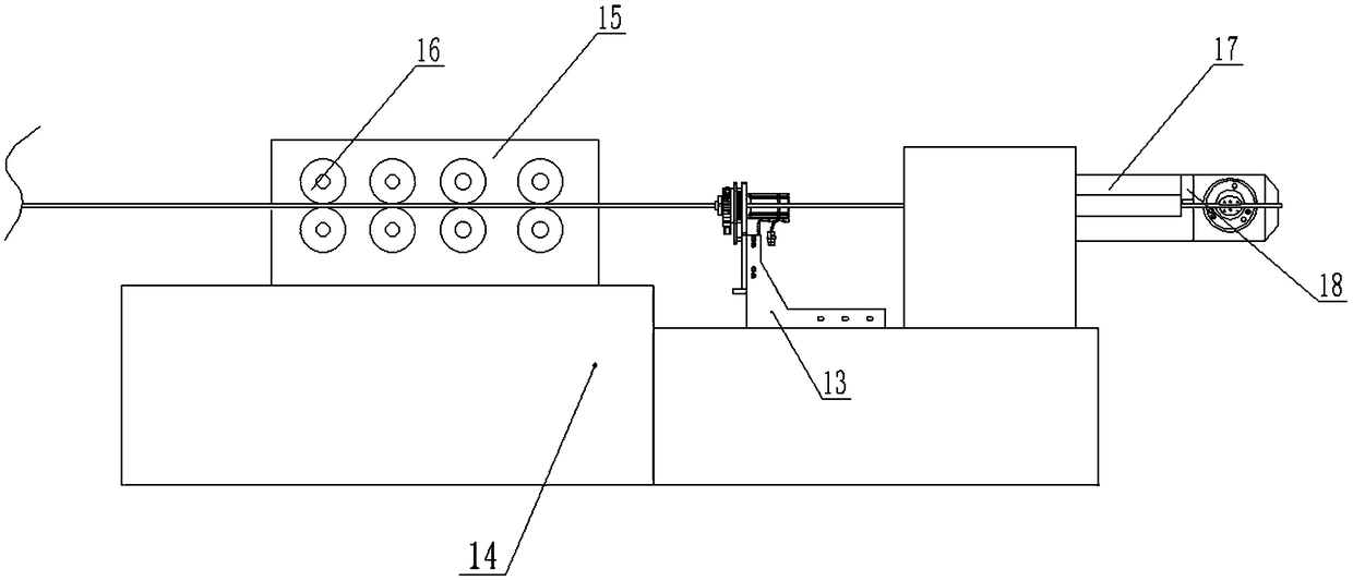
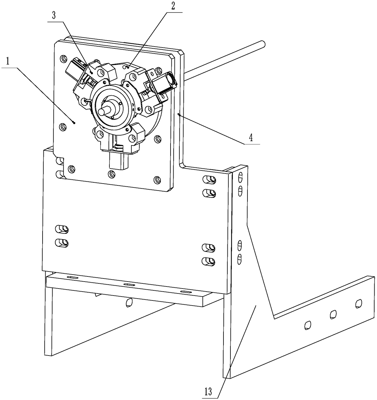
[0029] refer to Figure 1 to Figure 9 The shown hollow hook bending machine includes a frame 14 on which a hook wire feeding part 15 and a hook bending part are fixedly installed, and the hook bending part includes a bending machine Head 17, a mandrel head 27 and a rotating disk 19 are installed on the bending head 17, the mandrel head 27 is installed in the bending head 17, and the rotating disk 19 is connected to the bending head 17 On the telescopic rotary table 24, the mandrel head 27 is provided with a bending forming block 20, the rotating disk 19 is fixedly connected with a bending column, and the frame 14 is folded between the hook wire feeding part 15 and the hook. A hook pre-cutting device is also fixed between the bent parts. The hook pre-cutting device includes a first mounting plate 1, and a rotating disk 2 driven by a driving device is installed on the first mounting plate 1. The rotating disk 2 is fixedly connected with three cutting assemblies 3, the cutting a...


PUM


Abstract

The invention discloses a bending machine for a hollow lifting hook. The bending machine comprises a rack, wherein a lifting hook wire feeding part and a lifting hook bending part are fixedly mountedon the rack; the lifting hook bending part comprises a bending machine head; a lifting hook pre-cutting device is also fixed between the lifting hook wire feeding part and the lifting hook bending part on the rack; the lifting hook pre-cutting device comprises a first mounting plate; a rotary disc which is driven to rotate through a the driving device is mounted on the first mounting plate; the rotary disc is fixedly connected with at least one cutting assembly; each of the cutting assemblies comprises a telescopic mechanism; each of the telescopic mechanisms is connected with a correspondingcutter; the three cutting assemblies are uniformly and circularly arranged on the rotary disc; and the cutters on the cutting assemblies are positioned on the same circumference. According to the bending machine disclosed by the invention, before the hollow lifting hook is bent, a knife edge is pre-cut on the lifting hook, so that the phenomenon that the lifting hook cannot be deformed when the lifting hook is cut off is avoided.

Description

technical field [0001] The invention specifically belongs to the field of hollow hooks, and in particular relates to a hollow hook bending machine. Background technique [0002] The automobile exhaust pipe hook is the connecting part between the exhaust pipe and the automobile body, and the automobile exhaust pipe is fixed on the automobile body through the hook. The hook is divided into hollow hook and solid hook. After the solid hook is bent, it can be cut directly by the vertical cutting knife on the bending machine. After the hollow hook is bent, because the hollow hook It has a central hole, so the strength is low. If the vertical cutting knife is used to cut directly after bending, the hollow hook will be deformed and the entire hollow hook will be scrapped. In addition, when the solid hook is bent by the bending machine, it will not be deformed due to its strong strength, and when the hollow hook is bent, because the hollow hook is provided with a central hole, so T...

Claims


Application Information

Patent Timeline
Patent Type & Authority Patents(China)
IPC IPC(8): B21F45/16B21F1/00B21F11/00
CPCB21F1/006B21F11/00B21F45/16
Inventor 舒航
Owner 重庆针尖内燃机部件制造有限公司
Learn More