


Quick Research
Generate reliable direction feasibility study reports for your R&D in just a few steps.

Technical Q&A
Discover and master advanced knowledge NOW. Basics, ideas, possibilities, all at once.

Find Solutions
As an expert in R&D theories, this can generate solutions to your technical problems instantly.

Evaluate Feasibility
Analyze your overall solution with one click, know your potential R&D risks in advance.

Monitor Landscape
Get weekly tech updates, stay abreast of the latest tech innovations and key insights.
Multifunctional monitoring device
A monitoring device and a multi-functional technology, applied in the field of multi-functional monitoring devices, can solve the problems of camera pollution of the monitoring device, large energy consumption, affecting the monitoring effect, etc., and achieve the effect of increasing the monitoring range
- Summary
- Abstract
- Description
- Claims
- Application Information
AI Technical Summary
Problems solved by technology
Method used
Image

Examples
Embodiment 1
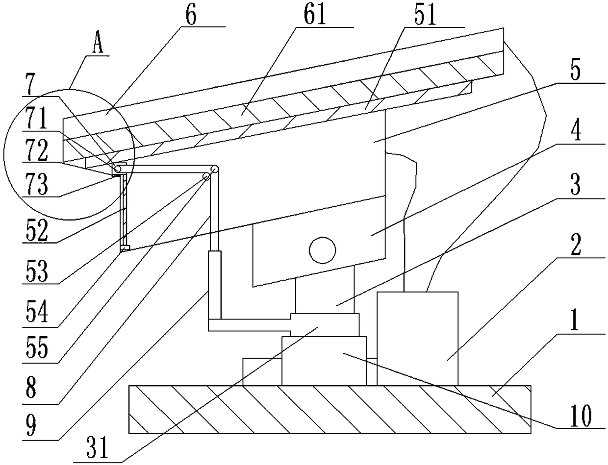
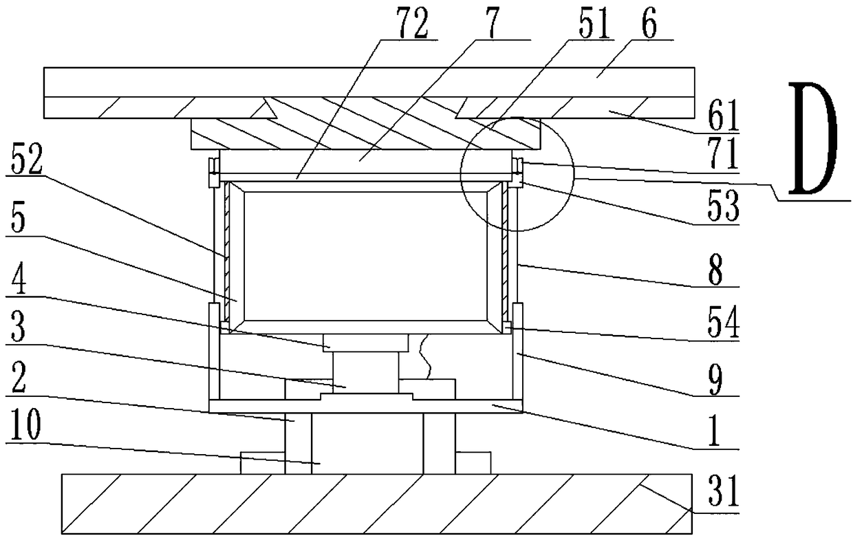
[0035] Such as Figure 1-4 As shown, a multifunctional monitoring device includes a monitoring body 5, a solar cell panel 6 and a base 1, the bottom of the solar cell panel 6 is provided with a bottom plate 61, and the bottom plate 61 is connected to the solar cell panel 6 by bolts. The bottom plate 61 is provided with a dovetail groove, and the top of the monitoring body 5 is provided with a top plate 51 matched with the dovetail groove, and the top plate 51 is fixedly connected with the monitoring body 5 by a fixed collar, and there are two camera windows near the monitoring body 5. Both sides are equipped with slide rails 52, the bottom of the slide rails 52 is equipped with a blocking plate 54, and the upper surface of the blocking plate 54 is also equipped with a buffer rubber pad, which can slow down the cleaning device from hitting the blocking plate 54 when moving down along the slide rails 52. strength. A cleaning device is slidably connected on the slide rail 52, an...
Embodiment 2
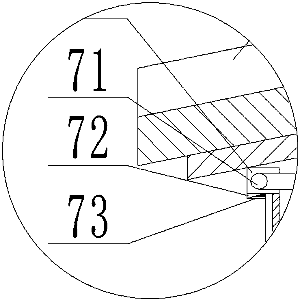
[0043] Such as Figure 1-4 As shown, this embodiment is further optimized on the basis of Embodiment 1. The cleaning device includes a cleaning plate 7, a brush bar 72 and a fine brush 73. The section of the cleaning plate 7 is U-shaped, and the two sides of the cleaning plate 7 are The inside of the wall is provided with a chute matched with the slide rail 52, the brush bar 72 is vertically arranged on the bottom of the cleaning plate 7, and the fine hair brush 73 is horizontally arranged on the brush bar 72, wherein the brush bar 72 and The cleaning board 7 is connected in a clamping manner, which is convenient for replacement, and the fine brush 73 can be used to better remove stains.
Embodiment 3
[0045] Such as Figure 1-4 As shown, the present embodiment is further optimized on the basis of Embodiment 1. Several small solar cell panels 6 are uniformly arranged on the solar cell panel 6, and the upper surface of the small solar cell panel 6 is coated with an anti-reflection film, so The small solar cell panels 6 are connected by flexible materials, and the edges of the solar cell panels 6 are provided with protection devices. The solar cell panels 6 connect each small solar cell panel 6 through flexible materials, and the flexible materials can be folded at will. Convenience and light weight can reduce the weight of the solar battery panel 6 to the greatest extent, so that the force on the monitoring device is small; at the same time, the reflective film can improve the utilization rate of light energy.
PUM
 Abstract
Description
Claims
Application Information
 - R&D Engineer
- R&D Manager
- IP Professional
- Industry Leading Data Capabilities
- Powerful AI technology
- Patent DNA Extraction
Browse by: Latest US Patents, China's latest patents, Technical Efficacy Thesaurus, Application Domain, Technology Topic, Popular Technical Reports.
© 2024 PatSnap. All rights reserved.Legal|Privacy policy|Modern Slavery Act Transparency Statement|Sitemap|About US| Contact US: help@patsnap.com