Multifunctional temperature and humidity control device for barn

A temperature and humidity control and multi-functional technology, applied in the direction of control input related to air characteristics, space heating and ventilation control input, application, etc., can solve the problems that do not meet the development needs of industrial equipment, difficult to achieve energy saving and emission reduction, high operating costs, etc. problem, to achieve the effect of improving storage stability and storage quality, good quality of low-temperature storage of grain, and saving energy consumption

Pending Publication Date: 2018-06-08
CHENGDU LANGBOWANG SCI & TECH DEV
View PDF7 Cites 4 Cited by
  • Summary
  • Abstract
  • Description
  • Claims
  • Application Information

AI Technical Summary

Problems solved by technology

The former has high operating costs, while the latter consumes a lot of energy when controlling the temperature of the warehouse space, and it is difficult for both of them to achieve the purpose of energy saving and emission reduction
At present, t

Method used


Image

  • Multifunctional temperature and humidity control device for barn
  • Multifunctional temperature and humidity control device for barn
  • Multifunctional temperature and humidity control device for barn

Examples


Embodiment 1

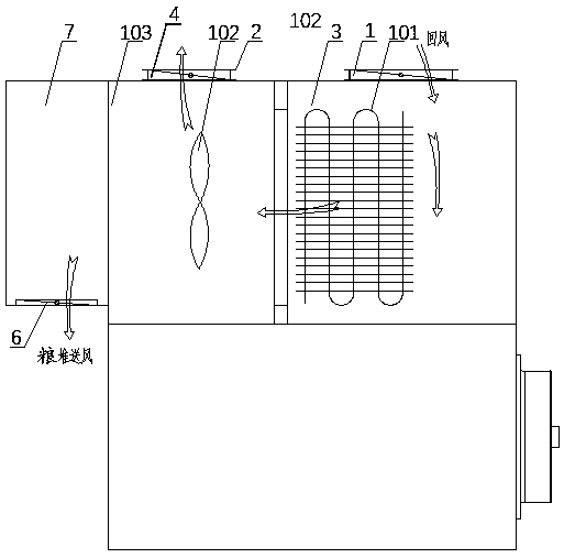
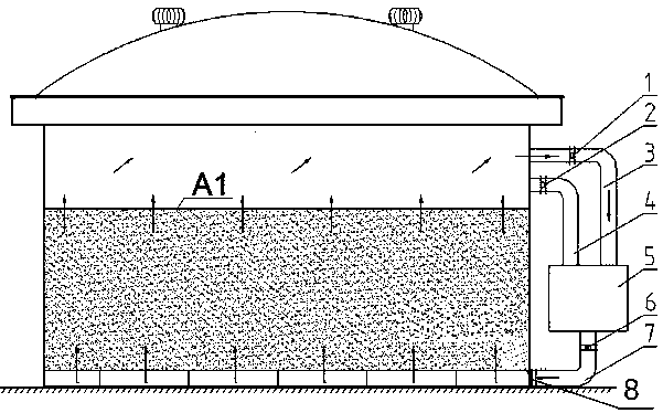
[0059] Example 1: as Figures 1 to 3 As shown, a multifunctional temperature and humidity control device for a granary, it includes a cooling device 5 arranged outside the granary, and the granary passes through the return air duct 3 in the warehouse and the air supply duct in the warehouse, which are arranged in the upper space of the warehouse wall. 4 is connected to the air path of the cooling equipment 5; it also includes an air duct 7 arranged on the grain pile, and the air duct 7 of the grain stack is connected to the bottom of the granary and connects the granary to the cooling equipment 5; the return air in the warehouse The pipeline 3 is provided with an in-store return air valve 1 , the in-store air supply pipeline 4 is provided with an in-store air supply valve 2 , and the grain-pile air-way pipeline 7 is provided with a grain-pile air-way valve 6 .

[0060] As preferred, such as Figure 4 As shown, the cooling device 5 includes a refrigeration system 101, one end ...

Embodiment 2

[0078] Embodiment 2: as figure 1 , image 3 with Figure 4 As shown, it is a temperature adjustment control method realized by using a technical solution of an optimally set cooling device 5. When the cooling device is used to cool the grain pile, the return air valve and the grain pile air path valve in the warehouse are opened. Close the air supply valve in the compartment. The return air in the warehouse is processed by the filter, and after being cooled and dehumidified by the evaporator in the refrigeration system through the return air pipe in the warehouse, the air reaches the air supply static pressure box, and the evaporating fan sends the low-temperature air into the grain stack air duct, and then passes through The grain stack air valve is sent into the granary through the vent of the cage on the ground of the grain depot. The low-temperature air passes through the grain pile and enters the refrigeration equipment through the return air duct connected to the spac...


PUM


Abstract

The invention discloses a multifunctional temperature and humidity control device for a barn and belongs to the field of grain storage and barn temperature and humidity control. The multifunctional temperature and humidity control device comprises temperature cooling equipment arranged at the outer part of the barn; the barn is connected with cooling equipment by an internal air return pipeline and an internal air supplying pipeline in the upper space of the barn wall in an air-path manner. The multifunctional temperature and humidity control device also comprises a grain-mass air path pipeline, wherein the grain-mass air path pipeline is connected at the bottom part of the barn and connects the barn and the cooling equipment in an air-path manner; an internal air return valve is arrangedin the internal air return pipeline; an internal air supplying valve is arranged in the internal air supplying pipeline; a grain-mass air path valve is arranged in the grain-mass air path pipeline. Compared with the prior art, the multifunctional temperature and humidity control device for the barn disclosed by the invention has the beneficial effects that mobile equipment cooling is improved intofixed installation, so that a foundation is laid for automatic grain storage; simultaneously, the functions of grain-mass internal cooling and grain-mass surface temperature control are achieved, theproblems of easy grain damage and easy fumigating corrosion when the temperature control equipment is installed in the barn are solved, and the function for selectable air supplying modes is achieved.

Description

technical field [0001] The invention belongs to the field of grain storage and granary temperature and humidity control, in particular to a multifunctional temperature and humidity control device for granaries. Background technique [0002] At present, my country's grain reserves store a large amount of grain. In order to ensure food safety and freshness, it is necessary to frequently cool down and control the temperature of the grain pile. Generally, it is necessary for the grain depot to use a mobile grain cooler or a grain storage unit with similar functions to cool down the inside of the grain pile. Due to the mobile use, it will take turns to cool down according to the temperature of each granary. And the grain cooling machine is big and inconvenient to move and use. At the same time, the heat on the roof of the granary is high, and the temperature is easy to rise; especially in summer, it is necessary to cool down the space inside the granary every day to keep the te...

Claims


Application Information

Patent Timeline
IPC IPC(8): F24F5/00F24F7/08F24F3/14F24F13/30F24F13/28F24F11/89F24F110/10F24F110/20
CPCF24F3/14F24F5/0007F24F7/08F24F13/28F24F13/30F24F2003/144
Inventor 刘照勇
Owner CHENGDU LANGBOWANG SCI & TECH DEV
Why Eureka
Try Eureka