
Semiconductor device, RC-IGBT, and method of manufacturing semiconductor device

A technology for semiconductors and devices, applied in the fields of semiconductor devices, RC-IGBTs and manufacturing semiconductor devices, can solve problems such as shortening the life of carriers, and achieve the effect of suppressing negative resistance

Pending Publication Date: 2018-06-05
RENESAS ELECTRONICS CORP
View PDF12 Cites 5 Cited by
  • Summary
  • Abstract
  • Description
  • Claims
  • Application Information

AI Technical Summary

Problems solved by technology

[0011] Japanese Unexamined Patent Application Publication No. 2013-197306 discloses an RC-IGBT in which a first lifetime controlled region is formed on the collector side in the IGBT region, whereby the flow of carriers on the emitter side The lifetime becomes long and the lifetime of carriers on the collector side is shortened, and a second lifetime controlled region is formed on the anode side in the FWD region, whereby the lifetime of carriers on the anode side is shortened and make the lifetime of the carriers on the cathode side longer

Method used


Image

  • Semiconductor device, RC-IGBT, and method of manufacturing semiconductor device
  • Semiconductor device, RC-IGBT, and method of manufacturing semiconductor device
  • Semiconductor device, RC-IGBT, and method of manufacturing semiconductor device

Examples


Embodiment Construction

[0044] For clarity of description, the following description and drawings are omitted and simplified as appropriate. In addition, the same components are denoted by the same reference numerals throughout the drawings, and overlapping descriptions will be omitted as necessary.

[0045] (Example)

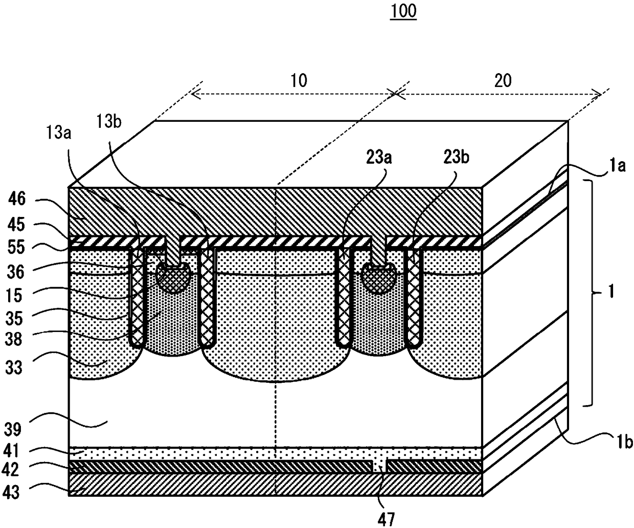
[0046] First, the outline of the semiconductor device according to the embodiment will be described. figure 1 It is a perspective view illustrating the outline of the semiconductor device according to the embodiment.

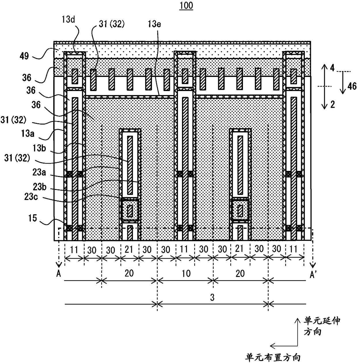
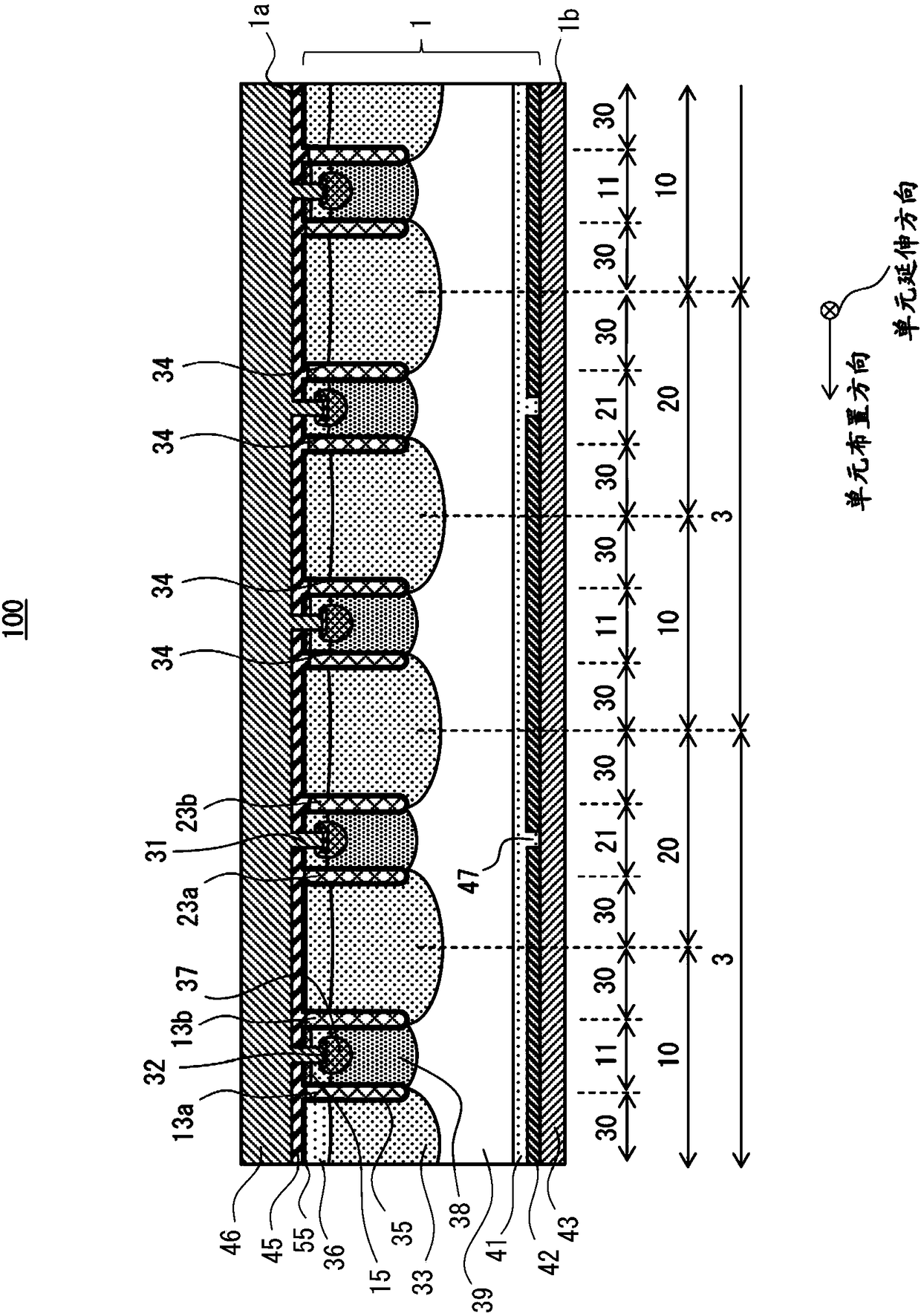
[0047] Such as figure 1 As shown in FIG. 1, the semiconductor device 100 includes: a semiconductor substrate 1 including a front surface 1a (first main surface) and a rear surface 1b (second main surface); an emitter electrode 46 and a gate wiring disposed on the front surface 1a (Not shown); and a collector electrode 43 provided on the rear surface. The semiconductor device 100 includes a first unit cell region 10 extending in one direction in a plane parallel to the fron...


PUM


Abstract

According to one embodiment, a semiconductor device 100 includes a semiconductor substrate 1 including a first principal surface and a second principal surface, an emitter electrode 46, a gate wiring49, a collector electrode 43, a first unit cell region 10 that is extended along one direction in a plane parallel to the first principal surface, and a second unit cell region 20 that is extended along one direction, in which the semiconductor substrate 1 of the first unit cell region 10 and the second unit cell region 20 includes an N- type drift layer 39, an N type hole barrier layer 38, a trench electrode 13, a P type body layer 36, an insulating film 35, an N type field stop layer 41, and a P+ type collector layer 42, and the second unit cell region 20 includes an N type cathode layer 47that is fitted into the collector layer 42 and is extended along one direction.

Description

[0001] Cross references to related applications [0002] This application is based on and claims the priority of Japanese Patent Application No. 2016-232547 filed on November 30, 2016, the entire content of which is incorporated herein by reference. Technical field [0003] The present application relates to semiconductor devices, RC-IGBTs, and methods of manufacturing semiconductor devices, and to semiconductor devices, RC-IGBTs, and methods of manufacturing semiconductor devices, for example, mounted on electric vehicles, other mechanical equipment, or the like using electric motors. Background technique [0004] Motor-driven power devices are installed on electric vehicles, other mechanical equipment, or the like that use motors. The power device driven by the motor includes, for example, an insulated gate bipolar transistor (hereinafter, it will be referred to as IGBT) and a freewheeling diode (hereinafter, it will be referred to as FWD) used with the IGBT. [0005] The reverse-c...

Claims


Application Information

Patent Timeline
Patent Type & Authority Applications(China)
IPC IPC(8): H01L29/739H01L21/336
CPCH01L29/66325H01L29/7393H01L29/407H01L29/4238H01L29/0619H01L29/0692H01L29/0834H01L29/66136H01L29/8613H01L29/66348H01L29/7397H01L29/4236H01L29/42324H01L27/0647H01L29/0696H01L29/0804H01L29/861
Inventor 山田和宽
Owner RENESAS ELECTRONICS CORP
Learn More