Monitoring equipment-based target object speed calculation method

A technology of monitoring equipment and speed calculation, which is applied in the field of intelligent transportation, can solve the problems of large speed error and large result error, and achieve the effect of improving precision, accuracy, and calculation accuracy

Inactive Publication Date: 2018-06-05
上海联合道路交通安全科学研究中心
View PDF6 Cites 8 Cited by
  • Summary
  • Abstract
  • Description
  • Claims
  • Application Information

AI Technical Summary

Problems solved by technology

[0003] At present, there are some deficiencies in the research method of using video to calculate vehicle speed, which are: first, most of the research fields involved in existing patents or professional papers are only aimed at the speed of participants in surveillance cameras without image distortion. Solving; second, it is limited to knowing the geometric parameters of the target, such as wheelbase, vehicle length, etc.; third, the result error is large. When the target and the video screen have a large angle, the obtained speed will be wrong. very big

Method used


Image

  • Monitoring equipment-based target object speed calculation method
  • Monitoring equipment-based target object speed calculation method
  • Monitoring equipment-based target object speed calculation method

Examples


Embodiment 1

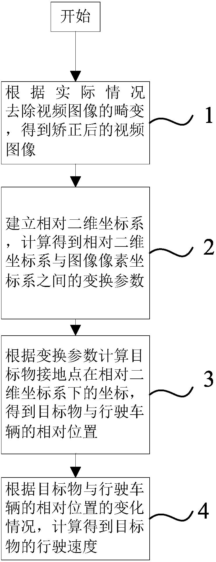
[0057] Such as figure 1 As shown, the purpose of this embodiment is to provide a method for calculating the speed of an object based on monitoring equipment, including the following steps:

[0058] 1) When the coordinates of the original video image in the image physical coordinate system are known, the distortion of the video image is removed to obtain a corrected video image;

[0059] 2) Establish a relative two-dimensional coordinate system, and calculate the transformation parameters between the relative two-dimensional coordinate system and the image pixel coordinate system;

[0060] 3) Calculate the coordinates of the ground point of the target object in the relative two-dimensional coordinate system according to the transformation parameters obtained in step 2), and obtain the relative position of the target object and the driving vehicle;

[0061] 4) According to the change of the relative position of the target object and the driving vehicle, the running speed of the...

Embodiment 2

[0134] Such as figure 1 As shown, the purpose of this embodiment is to provide a method for calculating the speed of an object based on monitoring equipment, including the following steps:

[0135] 1) When the coordinates of the original video image in the image physical coordinate system are unknown, the distortion of the video image is removed to obtain a corrected video image;

[0136] 2) Establish a relative two-dimensional coordinate system, and calculate the transformation parameters between the relative two-dimensional coordinate system and the image pixel coordinate system;

[0137] 3) Calculate the coordinates of the ground point of the target object in the relative two-dimensional coordinate system according to the transformation parameters obtained in step 2), and obtain the relative position of the target object and the driving vehicle;

[0138] 4) According to the change of the relative position of the target object and the driving vehicle, the running speed of t...


PUM


Abstract

The invention relates to a monitoring equipment-based target object speed calculation method, and aims at calculating speeds of target objects according to video images shot by monitoring equipment mounted on running vehicles. The method comprises the following steps of: judging whether a coordinate, under an image physical coordinate system, of an original video image is known or not, if the judging result is positive, removing distortion of the video image through coordinate transformation, and if the judging result is negative, removing the distortion of the video image through an image correction tool so as to obtain a corrected video image; establishing a relative two-dimensional coordinate system, and calculating a transformation parameter between the relative two-dimensional coordinate system and an image pixel coordinate system; calculating a coordinate, under the relative two-dimensional coordinate system, of a grounding point of a target object according to the normalized andnonlinearly optimized transformation parameter, so as to obtain relative positions of the target object and a running vehicle; and calculating a running speed of the target object according to changeconditions of the relative positions of the target object and the running vehicle. Compared with the prior art, the method has the advantages of removing image distortion and being small in result error and strong in operability.

Description

technical field [0001] The invention relates to the technical field of intelligent transportation, in particular to a method for calculating the speed of an object based on monitoring equipment. Background technique [0002] At present, with the widespread use of monitoring equipment (such as driving recorders, surveillance cameras, etc.) in vehicles and road traffic, we can easily understand the driving picture of the vehicle and even the occurrence of road traffic accidents from the recorded video images. For example, the driving recorder can record the real-time speed, acceleration and other information of the vehicle during driving, but we cannot directly know the relative position and speed information of the front target (such as vehicles, pedestrians, etc.) and the vehicle from the recorded picture; The driving recorder usually uses a monocular, wide-angle visual sensor, and there is a nonlinear relationship in its imaging system-distortion. Due to the existence of di...

Claims


Application Information

Patent Timeline
IPC IPC(8): G06K9/00
CPCG06V20/56
Inventor 何宇桐赵山林
Owner 上海联合道路交通安全科学研究中心
Why Eureka
Try Eureka