Pressurizing reverse-flow type organic garbage gasification furnace
A technology of organic waste and gasification furnace, which is applied in gasification process, manufacture of combustible gas, petroleum industry, etc. It can solve problems such as incomplete cracking and reduction of waste, insufficient oxygen supply for waste incineration, and slow drying speed of waste. Achieve the effect of novel structure, simple structure and fast drying speed
- Summary
- Abstract
- Description
- Claims
- Application Information
AI Technical Summary
Problems solved by technology
Method used
Image
Examples
Embodiment 1
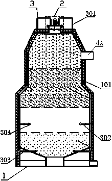
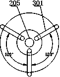
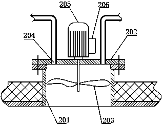
[0035] Such as figure 1 , 4 , 5, 6, and 7, a pressurized reflow type organic waste gasifier includes a gasifier body 1, and the inner space of the gasifier body 1 includes an oxidation zone, a reduction zone, and a cracking zone from bottom to top. and the drying area, and also includes a flue gas return device 3, the flue gas return device 3 includes a draft device 2 and a return device 3, the draft device 2 includes a draft tube 201, a cover plate 202 and a fan blade 203, and the draft tube 201 is installed on the top of the gasifier body 1 and communicates with the gasifier body 1, the cover plate 202 is installed on the upper end of the air induction pipe 201, and 2 to 4 return holes 204 are evenly arranged on the cover plate 202 along the circumferential direction , the fan blade 203 is installed inside the air induction pipe 201, and the fan blade 203 is connected with the motor 205 arranged on the cover plate 202 through a rotating shaft, the return device 3 includes a...
Embodiment 2
[0043] Such as Figure 1-7 As shown, the structure of the pressurized reflow type organic waste gasifier described in this embodiment is basically the same as that of Embodiment 1, except that the air induction device 2 is provided with a frequency converter 206 .
[0044] Both the air return main pipe 301 and the air return branch pipe 302 are provided with solenoid valves 303 .
[0045] The cover plate 202 is flexibly connected to the air duct 201 by means of flange bolts.
[0046] Spray heads 304 are installed at the ends of the air return main pipe 301 and the air return branch pipe 302 .
[0047] The smoke return valve 16, the water inlet valve 19, the drain valve 24 and the air intake valve 27 are electric valves.
PUM
 Abstract
Description
Claims
Application Information
 - R&D
- Intellectual Property
- Life Sciences
- Materials
- Tech Scout
- Unparalleled Data Quality
- Higher Quality Content
- 60% Fewer Hallucinations
Browse by: Latest US Patents, China's latest patents, Technical Efficacy Thesaurus, Application Domain, Technology Topic, Popular Technical Reports.
© 2025 PatSnap. All rights reserved.Legal|Privacy policy|Modern Slavery Act Transparency Statement|Sitemap|About US| Contact US: help@patsnap.com


