Sawtooth Vortex Field Acoustic Chaotic Cavitation Device
A vortex field and sawtooth technology, applied in the field of liquid flow chaotic reactors, to achieve the effect of improving efficiency and enhancing the effect of acoustic cavitation
- Summary
- Abstract
- Description
- Claims
- Application Information
AI Technical Summary
Problems solved by technology
Method used
Image

Examples
Embodiment 1
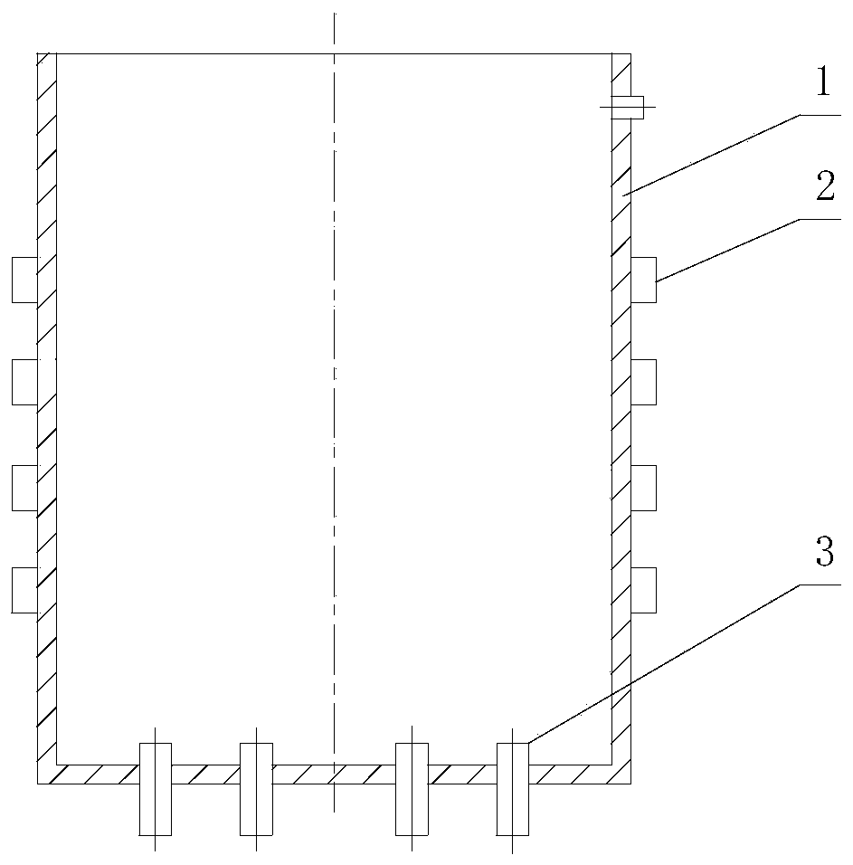
[0029] Such as figure 1 As shown, the sawtooth vortex field acoustic chaotic cavitation device of this embodiment is composed of a reactor 1, a sawtooth vortex field tube 3, and an ultrasonic transducer 2. The reactor 1 is a cylindrical structure with an open top. A water outlet is processed on the upper side wall, and a plurality of water inlets are processed at the bottom of the reactor 1, and a saw-toothed vortex field tube 3 is installed on the water inlet, and the water outlet direction of the saw-toothed vortex field tube 3 is parallel to the axis of the reactor , communicate with the water pump through the serrated vortex field pipe 3, and supply water to the reactor 1. The distance between one saw-toothed vortex field tube 3 and the adjacent saw-toothed vortex field tube 3 is 25 mm, and can be larger. The number of toothed vortex field tubes 3 depends on the size of the reactor 1 . The ultrasonic transducer 2 is installed on the side wall of the reactor 1, and the ult...
Embodiment 2
[0040] The sawtooth vortex field acoustic chaotic cavitation device of this embodiment is composed of a reactor 1, a sawtooth vortex field tube 3, and an ultrasonic transducer 2. The reactor 1 is a cylindrical structure with an open top. A water outlet is processed on the top, and a water inlet is processed on the bottom of the reactor 1, and a serrated vortex field tube 3 is installed on the water inlet. The ultrasonic transducer 2 is installed on the side wall of the reactor 1, and the ultrasonic transducer 2 is distributed in multiple layers from top to bottom, and the distance between the adjacent ultrasonic transducers 2 of the upper and lower layers is 70mm, each layer There are four ultrasonic transducers 2 installed on the same layer, and the four ultrasonic transducers 2 are evenly distributed on the same circumference, facing each other in pairs.
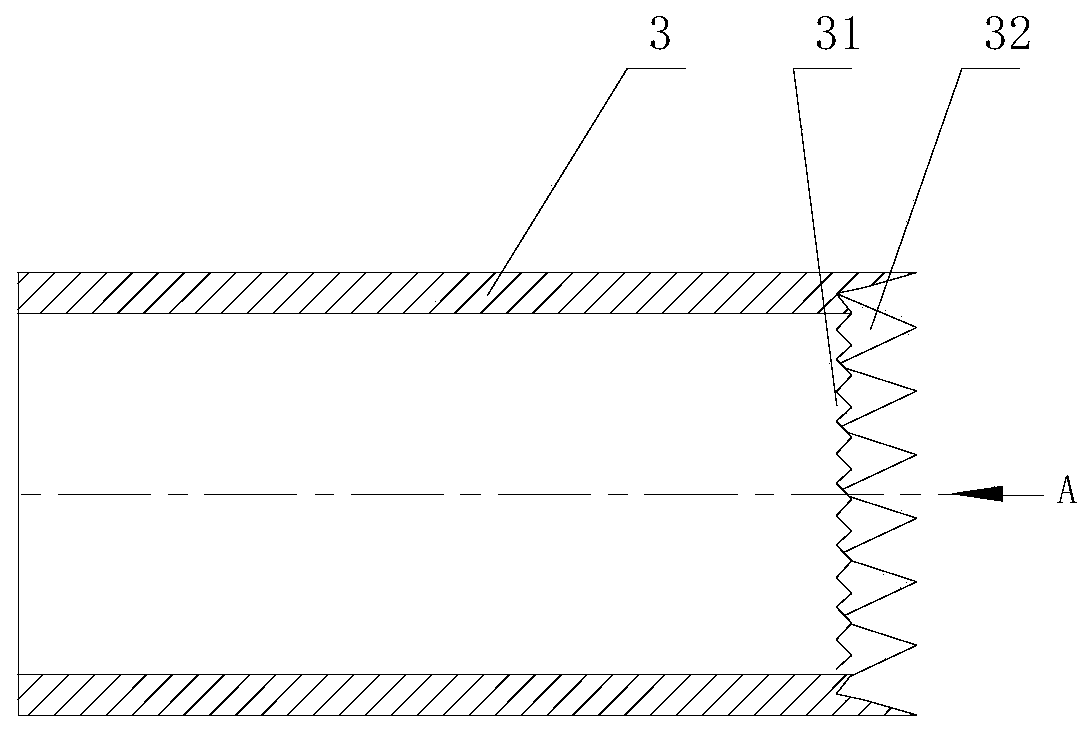
[0041] To further illustrate, the water outlet end of the serrated vortex field pipe 3 of this embodiment includes an in...
Embodiment 3
[0047] The sawtooth vortex field acoustic chaotic cavitation device of this embodiment is composed of a reactor 1, a sawtooth vortex field tube 3, and an ultrasonic transducer 2. The reactor 1 is a cylindrical structure with an open top. A water outlet is processed on the top, and a water inlet is processed on the bottom of the reactor 1, and a serrated vortex field tube 3 is installed on the water inlet. The ultrasonic transducer 2 is installed on the side wall of the reactor 1, and the ultrasonic transducer 2 is distributed in multiple layers from top to bottom, and the distance between the adjacent ultrasonic transducers 2 of the upper and lower floors is 55mm, each layer There are four ultrasonic transducers 2 installed on the same layer, and the four ultrasonic transducers 2 are evenly distributed on the same circumference, facing each other in pairs.
[0048] To further illustrate, the water outlet end of the serrated vortex field pipe 3 of the present embodiment include...
PUM
 Abstract
Description
Claims
Application Information
 - Generate Ideas
- Intellectual Property
- Life Sciences
- Materials
- Tech Scout
- Unparalleled Data Quality
- Higher Quality Content
- 60% Fewer Hallucinations
Browse by: Latest US Patents, China's latest patents, Technical Efficacy Thesaurus, Application Domain, Technology Topic, Popular Technical Reports.
© 2025 PatSnap. All rights reserved.Legal|Privacy policy|Modern Slavery Act Transparency Statement|Sitemap|About US| Contact US: help@patsnap.com