Side face excitation type ultrasonic processor and processing method
A processor and ultrasonic technology, applied in the direction of grain processing, fluid using vibration, etc., can solve the problems of low energy utilization efficiency, uneven energy distribution of sound field, cross-contamination of samples, etc., and achieve the effect of high energy utilization efficiency
- Summary
- Abstract
- Description
- Claims
- Application Information
AI Technical Summary
Problems solved by technology
Method used
Image
Examples
Embodiment approach
[0051] According to a preferred embodiment of the present invention, the width of the sample processing tank 2 is set to:
[0052]
[0053] or
[0054] or d<λ / 4 (three)
[0055] In the formula, d represents the width of the sample processing tank 2,
[0056] λ represents the wavelength,
[0057] Wherein, the value of n is a non-negative integer, preferably 0-10, more preferably 0-5.
[0058] The width d of the sample processing tank 2 should be as small as possible while satisfying the structural size requirements. When the sample processing tank 2 adopts acoustic field resonance to process samples, the width d of the sample processing tank 2 adopts the setting method of formula (1 or 2);
[0059] When the near-acoustic field is used to process samples in the sample processing tank 2, the width d of the sample processing tank 2 adopts the setting method of formula (3);
[0060] In the case where the wavelength of the acoustic wave and the number and arrangement of the...
Embodiment 1
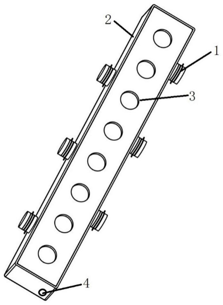
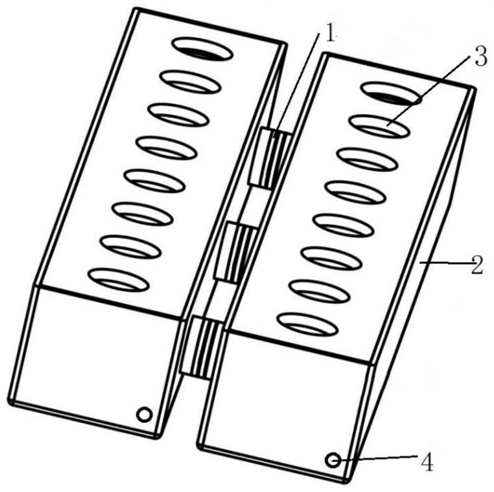
[0070] When the speed of sound in the solution is 1500m / s, and the width of the sample processing tank 2 is d=31.25mm (5λ / 4), at figure 1 The excitation voltage with a frequency of 60kHz is applied to a plurality of piezoelectric transducers 1 at the same time, and the piezoelectric transducers 1 work simultaneously in the sample processing tank 2 to generate a resonant sound field, and the cavitation effect is used to treat the samples placed on the sample test tube holder 3. The biological sample in the test tube is processed, and the water circulation hole 4 on the sample processing tank 2 is used to keep the temperature in the processing tank 3 constant.
Embodiment 2
[0072] When the speed of sound in the solution is 1500m / s, and the sample processing tank 2 width d=20mm, in figure 1 The excitation voltage with a frequency of 60 kHz is applied to a plurality of piezoelectric transducers 1 at the same time, and the piezoelectric transducers 1 work at the same time to generate a uniformly distributed near-acoustic field in the sample processing tank 2, and use the cavitation effect to treat the sample placed on the test tube holder 3 The biological sample in the sample test tube is processed, and the water circulation hole 4 on the sample processing tank 2 is used to keep the temperature in the processing tank 2 constant.
PUM
 Abstract
Description
Claims
Application Information
 - Generate Ideas
- Intellectual Property
- Life Sciences
- Materials
- Tech Scout
- Unparalleled Data Quality
- Higher Quality Content
- 60% Fewer Hallucinations
Browse by: Latest US Patents, China's latest patents, Technical Efficacy Thesaurus, Application Domain, Technology Topic, Popular Technical Reports.
© 2025 PatSnap. All rights reserved.Legal|Privacy policy|Modern Slavery Act Transparency Statement|Sitemap|About US| Contact US: help@patsnap.com


