
Guardrail cutting device

A technology for cutting devices and guardrails, applied in positioning devices, maintenance and safety accessories, clamping, etc., can solve the problems of inconvenient guardrail transmission, inability to process guardrails, and increase processing costs, and achieve compact structure, shallow keyway, and improved work efficiency effect

Inactive Publication Date: 2018-06-01
重庆立帆金属结构有限公司
View PDF0 Cites 0 Cited by
  • Summary
  • Abstract
  • Description
  • Claims
  • Application Information

AI Technical Summary

Problems solved by technology

However, the existing guardrails are manually operated during transmission, the work efficiency is low, and the transmission of the guardrails is inconvenient. During the cutting process, the guardrails are directly placed on the workbench. The use of the existing guardrail cutting can not process guardrails of different sizes, thus requiring multiple processing devices, which increases the processing cost

Method used


Image

  • Guardrail cutting device

Examples


Embodiment Construction

[0013] The present invention will be described in further detail below by means of specific embodiments:

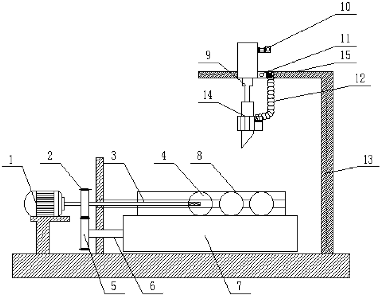
[0014] Instructions attached figure 1 The reference numerals include: motor 1, driving gear 2, flexible shaft 3, supporting round wheel 4, driven gear 5, transmission shaft 6, rotating round wheel 7, guardrail 8, cylinder 9, air intake check valve 10, air outlet Check valve 11, bellows 12, vertical bar 13, cutter 14, cross bar 15.

[0015] like figure 1 As shown, the guardrail cutting device includes a frame, a motor 1 is fixed on one side of the frame, the output shaft of the motor 1 is connected with a flexible shaft 3, and the frame is fixed with a shaft sleeve sleeved outside the flexible shaft 3. A plurality of supporting round wheels 4 are rotatably connected to the shaft sleeve, and the motor 1 drives one of the supporting round wheels 4 for pushing the guardrail 8 to translate through a flexible shaft 3 to rotate. The middle part of the output shaft of the motor...


PUM


Abstract

The invention belongs to the technical field of guardrail machining and particularly discloses a guardrail cutting device. The guardrail cutting device comprises a transmission mechanism and a cuttingmechanism and is characterized in that the transmission mechanism comprises a motor fixed on a frame, a soft shaft is connected to the output shaft of the motor, a shaft sleeve sleeving the soft shaft is fixed on the frame, a plurality of support wheels are rotatably connected to the shaft sleeve, the motor drives one of the support wheels used for pushing a guardrail to translate to rotate through the soft shaft, a drive gear is connected to the middle of the soft shaft, a driven gear meshing with the drive gear is connected to one side of the drive gear, a transmission shaft is connected tothe driven gear, a rotating wheel for driving the guardrail to rotate is fixedly connected to the transmission shaft, the frame comprises a transverse rod and a vertical rod, the cutting mechanism comprises a drive mechanism slidably connected to the transverse rod, and a tool is fixedly connected to the drive mechanism and located above the transmission mechanism. By the guardrail cutting device, the problems that an existing device is low in guardrail cutting efficiency, inconvenient in conveying and incapable of adapting to guardrails of different sizes and causes cutting deformation can be solved.

Description

technical field [0001] The invention belongs to the technical field of guardrail processing, and in particular relates to a guardrail cutting device. Background technique [0002] Guardrails are mainly used in some places such as roads, bridges, roadblocks, villa fences or roadside fences. It has good steel plasticity, high strength, corrosion resistance and other superior characteristics and is widely used. Since the guardrail is longer in size after production and molding, it needs to be cut according to the size requirements. However, the existing guardrails are manually operated during transmission, the work efficiency is low, and the transmission of the guardrails is inconvenient. During the cutting process, the guardrails are directly placed on the workbench. The use of existing guardrail cutting can not process guardrails of different sizes, thus requiring multiple processing devices, which increases the processing cost. Contents of the invention [0003] The obje...

Claims


Application Information

Patent Timeline
Patent Type & Authority Applications(China)
IPC IPC(8): B23D79/00B23Q3/06B23Q11/00
CPCB23D79/00B23Q3/06B23Q11/005
Inventor 周琪周强
Owner 重庆立帆金属结构有限公司
Learn More