
Reconstruction method and system for three-dimensional microstructure of material

A microstructure and reconstruction system technology, which is applied in the analysis of materials, material analysis using wave/particle radiation, image data processing, etc., can solve the problem of inaccurate division of components, achieve wide division and avoid secondary etching Effect

Active Publication Date: 2018-05-29
浙江隆劲电池科技有限公司
View PDF7 Cites 5 Cited by
  • Summary
  • Abstract
  • Description
  • Claims
  • Application Information

AI Technical Summary

Problems solved by technology

[0004] The embodiment of the present invention provides a method and system for reconstructing the three-dimensional microstructure of materials, which are used to obtain the three-dimensional distribution of material components, and solve the problem of inaccurate division of components by three-dimensional microstructure in the prior art

Method used


Image

  • Reconstruction method and system for three-dimensional microstructure of material
  • Reconstruction method and system for three-dimensional microstructure of material

Examples


Embodiment 1

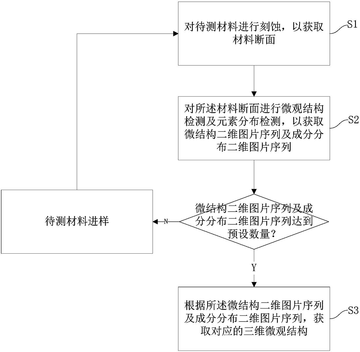
[0044] figure 1 It is a flowchart of a material three-dimensional microstructure reconstruction method in this embodiment, such as figure 1 As shown, a method for reconstructing the three-dimensional microstructure of a material in this embodiment includes:

[0045] S1. Etching the material to be tested to obtain the cross section of the material;

[0046] In this step, a focused ion beam device is used to etch the material to be tested to obtain a cross section of the material; the focused ion beam is an ion beam generated by a Ga ion source, and the focused ion beam is accelerated by an ion gun to etch the material; the focused ion beam The accelerating voltage is adjusted according to different material properties.

[0047] In this embodiment, the accelerating voltage intensity of the focused ion beam emitting gun can be set to 20kV, and the generated accelerated ion beam can be used to perform cross-sectional etching on the material to be tested, and the cross-sectional ...

Embodiment 2

[0072] In this embodiment, before the reconstruction of the three-dimensional microstructure of the material, it also includes: a material preparation process, specifically:

[0073] A certain amount of lithium-ion battery cathode active material (lithium cobalt oxide), conductive agent (carbon black), and binder (PVDF) are fully dry-ground according to a certain ratio, and a certain amount of NMP (N-methylpyrrolidone) is added to carry out wet grinding;

[0074] The ground slurry is scraped on the aluminum foil to form a porous material coating with a thickness of about 100 microns;

[0075] Cut the material into a size of 3mm×3mm, and conduct gold evaporation;

[0076] The gold-plated sample is placed on the sample stage, and the detection area is determined by the scanning electron microscope device.

[0077] In this embodiment, by using the three-dimensional microstructure reconstruction method, using the distribution of elemental components as the standard for the divis...

Embodiment 3

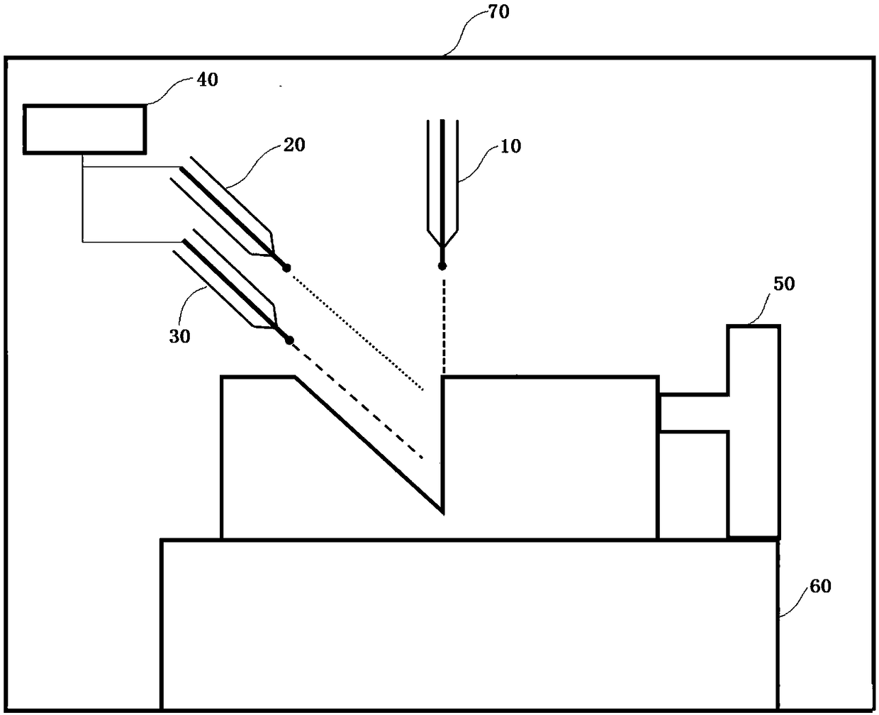
[0079] figure 2 It is a structural diagram of a material three-dimensional microstructure reconstruction system in this embodiment, such as figure 2 As shown, a material three-dimensional microstructure reconstruction system in this embodiment includes:

[0080] The focused ion beam device 10 is used to etch the material to be tested to obtain a cross section of the material;


PUM

PropertyMeasurementUnit
thicknessaaaaaaaaaa

Abstract

The invention discloses a reconstruction method and system for a three-dimensional microstructure of a material. The method comprises the following steps: S1, etching a material to be detected to obtain a material section; S2, carrying out microstructure detection and element distribution detection on the material section, so as to obtain a microstructure two-dimensional picture sequence and a component distribution two-dimensional picture sequence; S3, obtaining the corresponding three-dimensional microstructure according to the microstructure two-dimensional picture sequence and the component distribution two-dimensional picture sequence. According to the reconstruction method and system, disclosed by the invention, two-dimensional distribution of material components can be obtained; thethree-dimensional microstructure and component distribution are obtained in primary section etching and secondary etching of the material section is avoided; the element component distribution is used as standards for dividing solid-phase components of the material and is more accurate than an existing method of utilizing gray threshold, and the division of material component types is wider.

Description

technical field [0001] The invention relates to the field of material microstructure and composition characterization, and in particular to a method and system for reconstructing a three-dimensional microstructure of a material. Background technique [0002] The microstructure and composition distribution information of materials are the decisive factors to determine the physical and chemical behavior of materials. However, for a long time, microstructural characterization and component distribution analysis have been independent. The scanning electron microscope is one of the main tools for testing the microstructure of materials. The scanning electron microscope can measure the microstructure of materials from macroscopic to microscopic and even nanometer-sized. , phase distribution, interface characteristics, impurity distribution, etc.). EDS energy spectrometer (X-ray Energy Dispersive Spectroscopy, referred to as EDS), also known as microscopic electron probe, is an i...

Claims


Application Information

Patent Timeline
Patent Type & Authority Applications(China)
IPC IPC(8): G01N23/2206G06T7/11G06T7/136G06T17/00
CPCG01N23/2206G06T7/11G06T7/136G06T17/00G06T2207/10016
Inventor 程昀林月刘晋李正斌
Owner 浙江隆劲电池科技有限公司
Learn More