Al technical title is built by PatSnap Al team. It summarizes the technical point description of the patent document.
A crack identification and bridge technology, applied in image communication, aircraft parts, transportation and packaging, etc., can solve the problems of easy shaking, power system interference, poor detection and identification effect, etc., and achieve the effect of not easy to shake and uniform air resistance.
Inactive Publication Date: 2018-05-29
TIANJIN UNIV
View PDF15 Cites 4 Cited by
Summary
Abstract
Description
Claims
Application Information
AI Technical Summary
This helps you quickly interpret patents by identifying the three key elements:
Problems solved by technology
Method used
Benefits of technology
Problems solved by technology
[0003] At present, most of the detection and identification of bridge cracks in construction projects are carried out through human judgment and instrument detection. Few drones are used to investigate and identify cracks. A few bridge crack identification devices still have some The disadvantages are that many devices do not have the effect of lightning protection in the environment of lightning strikes in rainy days, which will cause damage to the power components inside the device, and the power system will be seriously disturbed. The stability of the device is not good when it is stored and shelved. The air resistance is uneven, easy to shake, resulting in poor detection and identification, easy to damage, troublesome to operate, and the price is too high
Method used
Image
Click on the blue label to locate the original text in one second.
Reading with bidirectional positioning of images and text.
Examples
Embodiment Construction
[0022] The following will clearly and completely describe the technical solutions in the embodiments of the present invention with reference to the accompanying drawings in the embodiments of the present invention. Obviously, the described embodiments are only some, not all, embodiments of the present invention. Based on the embodiments of the present invention, all other embodiments obtained by persons of ordinary skill in the art without making creative efforts belong to the protection scope of the present invention.
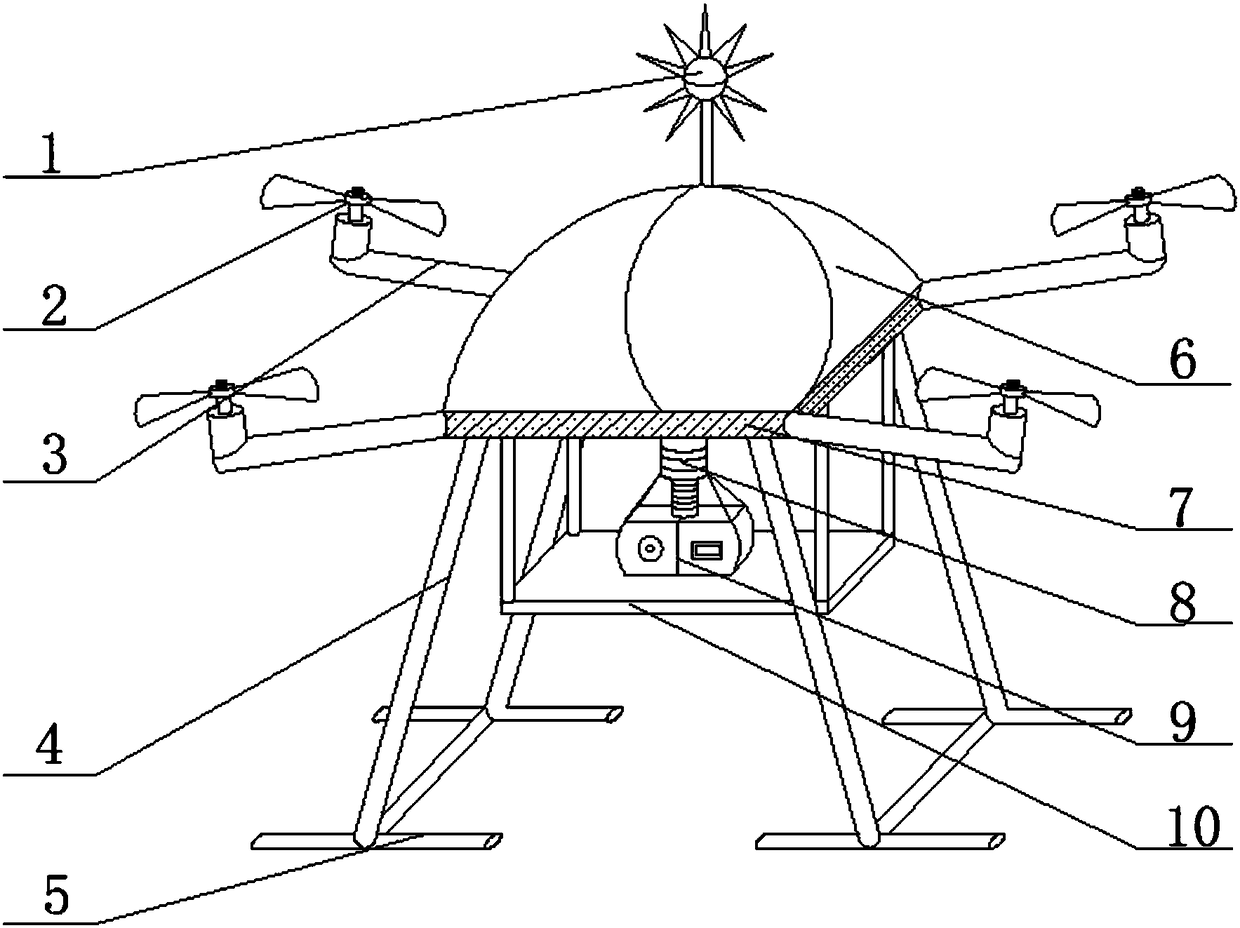
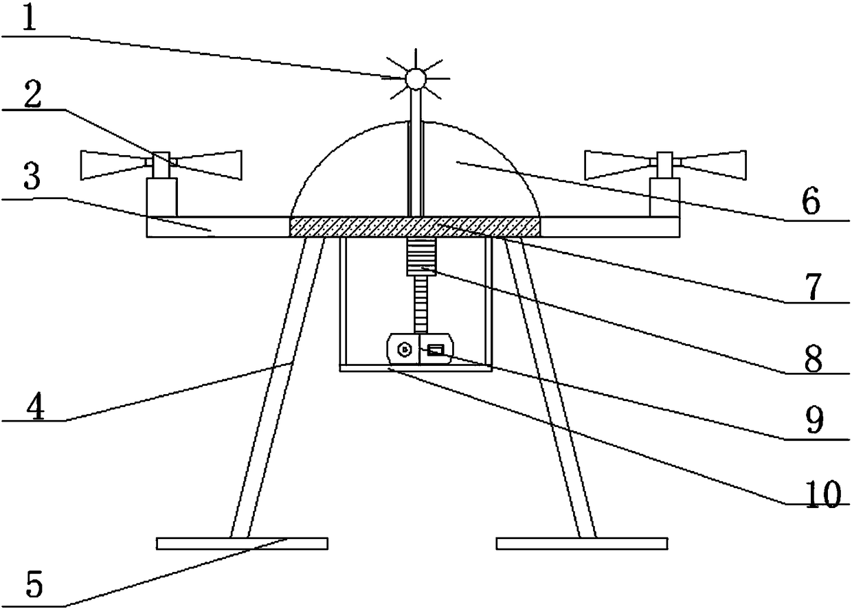
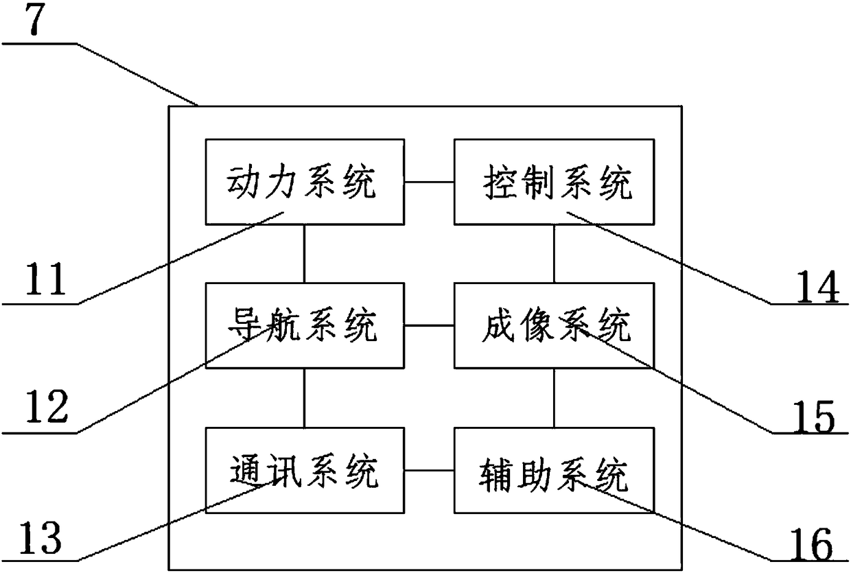
[0023] see Figure 1-4 As shown, a bridge crack identification device based on unmanned aerial vehicle imaging includes a numerical control platform 7, the top of the numerical control platform 7 is provided with a cover 6, and the top of the cover 6 is provided with a lightning rod 1; A screw rod 3 is installed at four corners, and the end of the screw rod 3 is equipped with a propeller 2; the four corners of the bottom of the numerical control platform 7 are...
PUM
Abstract
The invention discloses an unmanned aerial vehicle imaging-based bridge crack identification device, which comprises a lightning rod, propellers, screw rods, support rods, crossbars, a sealing cover,a numerical control platform, a connecting rod, a camera, a fixed platform, a power system, a navigation system, a communication system, a control system, an imaging system, an auxiliary system, a wireless network, a power supply, an led light, an alarm system, a memory and a voice prompt module. The unmanned aerial vehicle imaging-based bridge crack identification device is additionally providedwith the lightning rod, the device is prevented from being damaged by lightning strike when working in a thunderstorm, thus the operation of the internal power system of the device is not interfered,the combination and assembly of the support rods and the crossbars enables the device more stable in storage, the device runs more smoothly, the air resistance is more even, under the adjustment of the control system and the imaging system, the camera can photograph the bridge in all directions, the communication system and the imaging system transmit signals to a receiving station, and thus simpleness and practicality are achieved.
Description
technical field [0001] The invention belongs to the technical field of application of UAV identification devices, and relates to a bridge crack identification device, in particular to a bridge crack identification device based on UAV-borne imaging. Background technique [0002] Bridge cracks refer to a phenomenon in which the surface of the bridge is cracked due to many reasons such as load, its own materials, and external substances. The damage caused by bridge cracks is huge, so it is necessary to regularly and comprehensively check the surface and interior of the bridge. Whether cracks appear, eliminate safety hazards in time, and ensure the safety of pedestrians. Therefore, it is necessary to provide a device that can independently identify whether there are cracks in the bridge and determine the cause. [0003] At present, most of the detection and identification of bridge cracks in construction projects are carried out through human judgment and instrument detection. F...
Claims
Application Information
Patent Timeline
Application Date:The date an application was filed.
Publication Date:The date a patent or application was officially published.
First Publication Date:The earliest publication date of a patent with the same application number.
Issue Date:Publication date of the patent grant document.
PCT Entry Date:The Entry date of PCT National Phase.
Estimated Expiry Date:The statutory expiry date of a patent right according to the Patent Law, and it is the longest term of protection that the patent right can achieve without the termination of the patent right due to other reasons(Term extension factor has been taken into account ).
Invalid Date:Actual expiry date is based on effective date or publication date of legal transaction data of invalid patent.