
Flat cable lifting device for stacker

A flat cable and stacker technology, applied in the direction of lifting devices, etc., can solve the problems of interfering with the operation of other parts, reducing the service life of cables, and the failure of the cargo platform to work normally.

Inactive Publication Date: 2019-01-29
TAIYUAN OTTLE LOGISTICS TECH CO LTD
View PDF0 Cites 0 Cited by
  • Summary
  • Abstract
  • Description
  • Claims
  • Application Information

AI Technical Summary

Problems solved by technology

During the working process of the stacker, the goods placed on the forks move in the first direction through the movement of the stacker along the direction of the roadway, and the displacement in the second direction is realized through the up and down movement of the loading platform. To realize the displacement in the third direction, the displacement in all directions requires the drive of the motor, the operation of the motor requires power supply, and the cable transports electricity; the loading platform is an important component of the stacker, and flat cables are generally used as the The motor and each switch supply power, one end of the flat cable is connected to the power supply in the power supply cabinet, and the other end is connected to the cargo platform; when the stacker moves along the roadway, the cargo platform moves up and down relative to the stacker, and the flat cable also As the loading platform rises and falls, and because the stacker moves horizontally, the flat cable shakes back and forth with the stacker, causing the flat cable to easily get stuck on other components during the lifting process, interfering with the operation of other components , which reduces the service life of the cable, and may even cause the loading platform to fail to work due to the sudden break of the flat cable

Method used


Image

  • Flat cable lifting device for stacker
  • Flat cable lifting device for stacker
  • Flat cable lifting device for stacker

Examples


Embodiment Construction

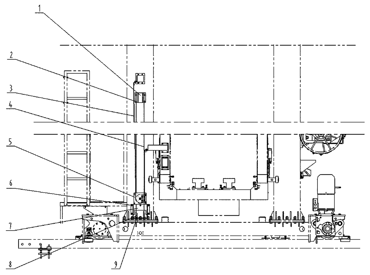
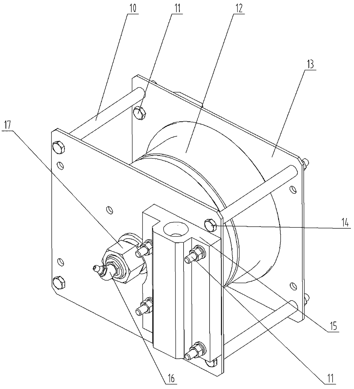
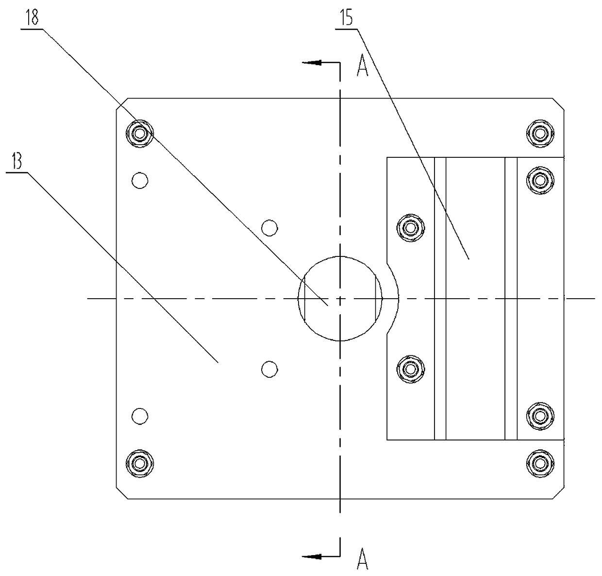
[0013] As shown in the figure, the present invention mainly includes bracket (1) 1, screw 2, flat cable 3, steel wire rope 4, lifting wheel assembly 5, screw 6, bracket (2) 7, pull rod 8 from top to bottom; bracket (1) 1 and support (two) 7 are installed in the middle lower end position of stacker column 24 with screw 2,6 respectively, and support (two) 7 installations can fix the pull bar 8 of wire rope 4, and fix with nut. The lifting wheel assembly 5 includes a pulley mounting sleeve 10, bolts 11, pulleys 12, pulley mounting plates 13, bolts 14, wire rope guide sleeves 15, oil cups 16, nuts 17, pulley shafts 18, bearings 19, pulley shaft spacers 20 The pulley 12 is installed on the pulley shaft 18 through the deep groove ball bearing 19, the pulley shaft spacer 20 of the compression bearing 19 is installed at the two ends of the pulley shaft 18, and the pulley shaft 18 is inserted in the center position between the two pulley mounting plates 13, The leftmost end is fixed wi...


PUM


Abstract

The invention relates to a flat cable lifting device for a stacker, and aims to prevent a flat cable from shaking and being worn. The flat cable lifting device for the stacker comprises a lifting wheel assembly, pull rods and supports, wherein the lifting wheel assembly comprises a pulley, pulley installation plates, pulley installation sleeves, a steel wire rope, steel wire rope guide sleeves, apulley shaft and a bearing; the pulley is arranged on the pulley shaft through the bearing; the pulley shaft is inserted between the pulley installation plates; one end of the pulley shaft is fixed through a nut; the pulley installation sleeves are arranged on four corners between the pulley installation plates through bolts; the two steel wire rope guide sleeves are fixed to the front positions and the back positions on the pulley installation plates through bolts; one end of the steel wire rope is fixed onto the pull rod; the other end of the steel wire rope sequentially penetrates through the steel wire rope guide sleeves, the support and the steel wire rope guide sleeves so as to be fixed onto the other pull rod; the two supports are arranged at the positions, close to the lower ends,in the middles of stand columns of the stacker through screws; and the pull rod capable of fixing the steel wire rope is arranged on one support.

Description

technical field [0001] The invention relates to a circuit conveying auxiliary device for a three-dimensional storage stacker, in particular to a flat cable lifting device for a stacker. Background technique [0002] With the development of the modern logistics industry, the three-dimensional warehouse industry has become a trend. As a kind of transportation equipment for the three-dimensional warehouse, the stacker crane has more and more diversified structures and functions. During the working process of the stacker, the goods placed on the forks move in the first direction through the movement of the stacker along the direction of the roadway, and the displacement in the second direction is realized through the up and down movement of the loading platform. To realize the displacement in the third direction, the displacement in all directions requires the drive of the motor, the operation of the motor requires power supply, and the cable transports electricity; the loading ...

Claims


Application Information

Patent Timeline
IPC IPC(8): B66F9/07B66F9/075
CPCB66F9/07B66F9/075
Inventor 王磊许朝阳何红兵陈洁田李川唐婷婷常小虎
Owner TAIYUAN OTTLE LOGISTICS TECH CO LTD
Learn More