
Candle filter element

A candle-type filter and filter element technology, which is applied in the field of filter elements, can solve problems such as inconvenient use, heavy secondary pollution, and low filtration efficiency, and achieve the effects of large flow rate, good effect, and reduced contact area

Pending Publication Date: 2018-05-29
YNT PETROCHEM MACHINERY EQUIP
View PDF1 Cites 1 Cited by
  • Summary
  • Abstract
  • Description
  • Claims
  • Application Information

AI Technical Summary

Problems solved by technology

[0003] Existing sand filters and metal filters have disadvantages such as low filtration efficiency, heavy secondary pollution, poor corrosion resistance, and high cost.
For example, a kind of sequential unloading candle filter announced by Chinese patent CN102166443A has complex structure, inconvenient use and poor versatility

Method used


Image

  • Candle filter element
  • Candle filter element
  • Candle filter element

Examples


Embodiment 1

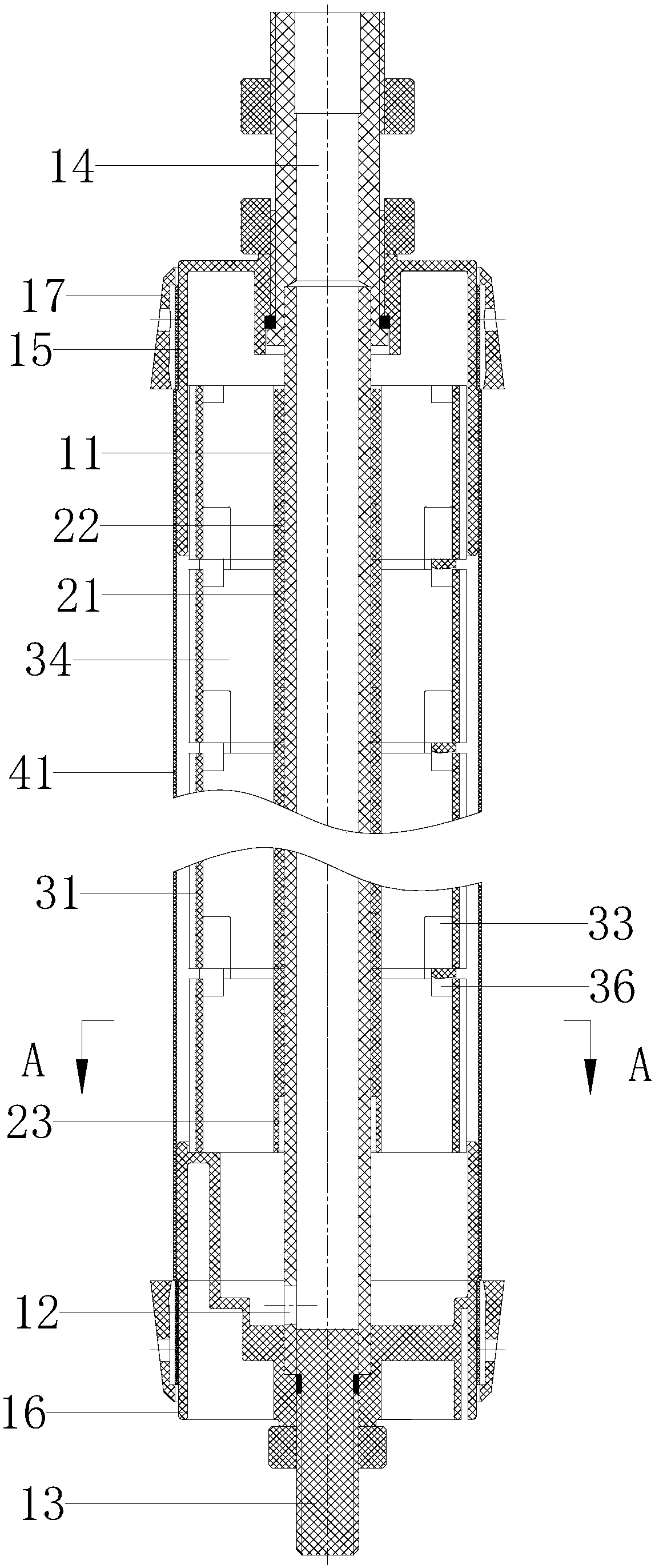
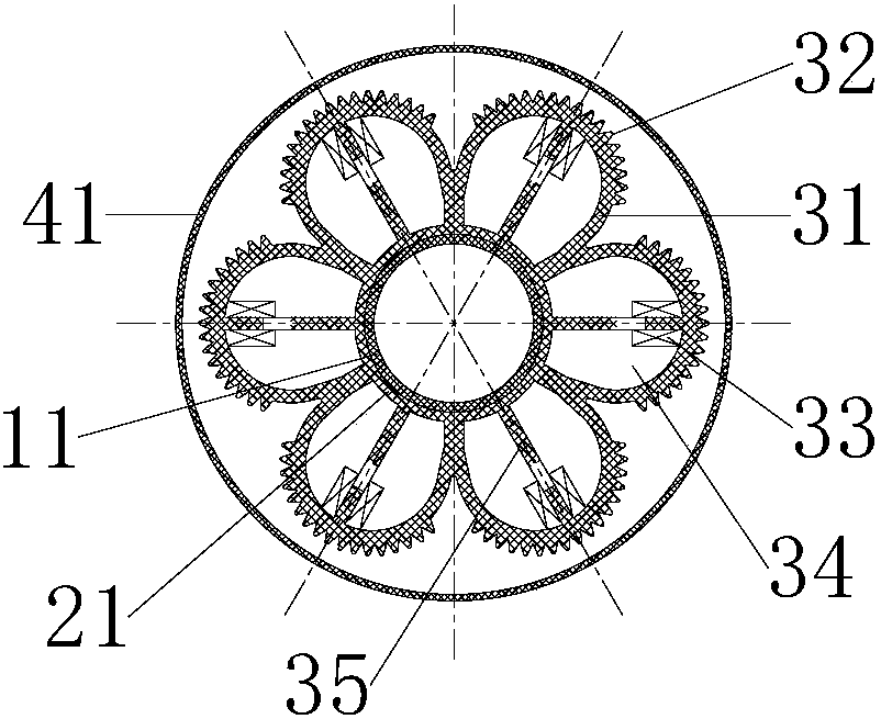
[0038] Such as figure 1 , figure 2 and image 3 As shown, a candle filter element includes an upper end cap 15 , a lower end cap 16 , a central tube 11 , a filter element skeleton 21 , a filter frame 31 and a filter cloth 41 .

[0039] The central pipe 11 is provided with a liquid inlet 12, and the liquid inlet 12 is located at the bottom of the central pipe 11; the bottom of the central pipe 11 is equipped with a lower joint 13 and a lower end cover 16, and the lower joint 13 is located below the liquid inlet 12, and the lower joint 13 blocks the bottom of the central tube 11, the top of the central tube 11 is equipped with an upper connecting pipe 14 and an upper end cover 15, and the upper connecting pipe 14 communicates with the central pipe 11; the filter element skeleton 21 is a round pipe, and a plurality of filter element skeletons 21 are stacked and installed, and the filter element skeleton One end of 21 is provided with inserting ring 22, and the other end is pro...

Embodiment 2

[0056] On the basis of the above embodiments, the outer surface of the filter frame 31 is provided with elongated grooves, the grooves are perpendicular to the axis of the filter core frame 21 , there are no less than two grooves, and the grooves intersect with the protrusions 32 .

[0057] The groove can increase the gap between the filter cloth 41 and the filter frame 31, reduce the contact area between the filter cloth 41 and the filter frame 31, and improve the flow of liquid.

Embodiment 3

[0059] On the basis of the above embodiments, the surface of the filter frame 31 in contact with the filter cloth 41 is provided with through holes. Adding through holes on the filter frame 31 can further reduce the contact area between the filter cloth 41 and the filter frame 31 , maximize the flow of liquid and accelerate the filtration speed.


PUM


Abstract

The invention relates to a candle filter element which comprises an upper end cover, a lower end cove, a center pipe, a filter element framework, less than three filter frames and a filter fabric. A liquid inlet hole is formed in the center pipe and positioned at the bottom of the center pipe, a lower connector and the lower end cover are mounted at the bottom of the center pipe, the lower connector is positioned below the liquid inlet hole, the bottom of the center pipe is plugged by the lower connector, the upper connecting pipe and the upper end cover are mounted at the top of the center pipe, the upper connecting pipe is communicated with the center pipe, the filter element framework is provided with a circular pipe and sleeves the center pipe, filter frames uniformly surround the outer circumferential surface of the filter element framework, gaps are formed among the filter frames, liquid passing holes are formed in the filter frames and parallel to the axis of the filter elementframework, the filter fabric sleeve the filter frames, two ends of the filter fabric are fixed on the upper cover and the lower end cover through hoops, the filter frames are communicated with the upper end cover and the lower cover, and the lower end cover is communicated with the liquid inlet hole. The filter element is good in filtering effect, low in cost and wide in application range.

Description

technical field [0001] The invention relates to a filter element, in particular to a candle filter element. Background technique [0002] In titanium dioxide, viscose fiber, polysilicon (hydrofluoric acid and nitric acid) industries, there are a large number of highly corrosive solutions that require solid-liquid separation during the production process. Untreated solutions cannot meet product quality requirements and will cause environmental damage. pollute. In the market situation where the supply of titanium dioxide and viscose fiber exceeds demand, and under severe environmental pressure, choosing a suitable filter element is crucial to the production efficiency and product quality of the product. [0003] The existing sand filters and metal filters have the disadvantages of low filtration efficiency, heavy secondary pollution, poor corrosion resistance, and high cost. Such as the Chinese patent CN102166443A discloses a sequential discharge candle filter, which has com...

Claims


Application Information

Patent Timeline
Patent Type & Authority Applications(China)
IPC IPC(8): B01D29/15B01D29/52B01D29/68B01D29/82
CPCB01D29/15B01D29/52B01D29/68B01D29/82
Inventor 赵坤念
Owner YNT PETROCHEM MACHINERY EQUIP
Learn More