
A fully mechanized excavator foam dust suppression device installation mechanism

A technology of a dust suppression device and an installation mechanism, which is applied to slitting machinery, earth-moving drilling, etc., can solve the problems of cumbersome installation operation, shortened service life, time-consuming and laborious, etc., and achieves the solution of cumbersome installation operation, improves stability, and facilitates installation. Effect

Inactive Publication Date: 2020-11-06
BEIJING HAOHUA ENERGY RESOURCE +1
View PDF12 Cites 0 Cited by
  • Summary
  • Abstract
  • Description
  • Claims
  • Application Information

AI Technical Summary

Problems solved by technology

[0002] In the prior art, the foam dust suppression device is installed on the fixing bolts of the cantilever section of the fully mechanized excavator and the reducer. Due to the relatively high hardness of the rock in the roadway, the vibration of the cutting arm of the fully mechanized excavator is relatively large during excavation. After installation, the fixing bolts may be damaged. The damage of the reducer or the cantilever section affects production; in the prior art, the foam dust suppression device is easily damaged due to long-term vibration during use, and the service life is shortened; in the prior art, the installation and operation of the foam dust suppression device It is cumbersome, time-consuming and labor-intensive, so a fully mechanized excavator foam dust suppression device installation mechanism is needed to solve the above problems

Method used


Image

  • A fully mechanized excavator foam dust suppression device installation mechanism
  • A fully mechanized excavator foam dust suppression device installation mechanism
  • A fully mechanized excavator foam dust suppression device installation mechanism

Examples


specific Embodiment approach

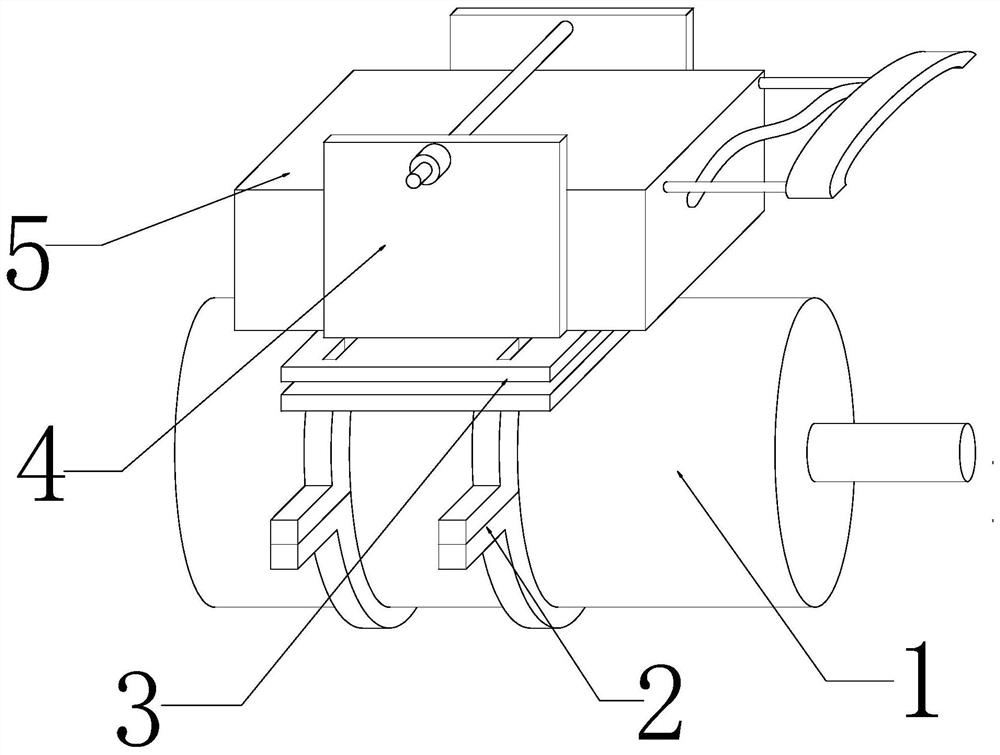
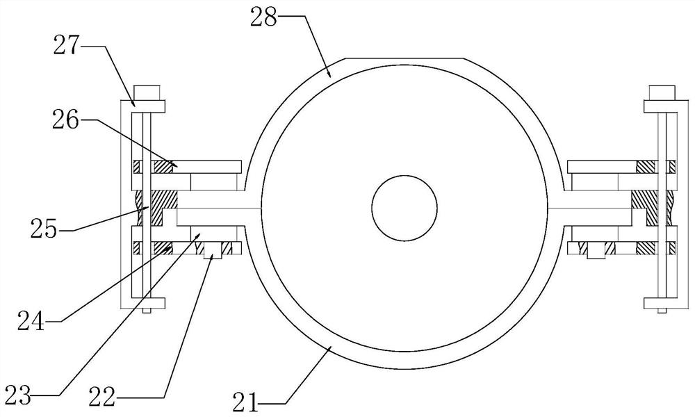
[0025] Specific embodiments: When the staff uses this mechanism, the upper hoop 28 and the lower hoop 21 are respectively assembled on the upper and lower ends of the annular side of the reducer 1, and the upper hoop 28 and the lower hoop 21 are connected by bolts 22, Then tighten the nut 23, and then the staff rotates the turntable, the turntable rotates to drive the two-way screw 25 to rotate, and the ball nut pair converts the rotation of the two-way screw 25 into linear motion, so that the ball nut seat drives the upper splint 26 to move downward, thereby Move the upper splint 26 to a position close to the upper end surface of the bolt 22, and the ball nut seat 2 drives the lower splint 24 to move, so that the lower splint 24 moves to a position close to the lower end surface of the nut 23. This design improves the upper The stability of the connection between the hoop 28 and the lower hoop 21.

[0026] During the use of this mechanism, the vibration generated by the reducer ...


PUM


Abstract

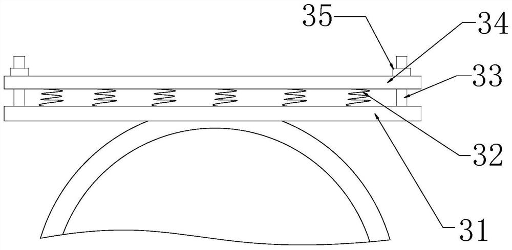
The invention provides an installation mechanism of a roadheader foam dust removal device. The installation mechanism comprises a lower hoop, a lower clamping plate, a two-way lead screw, an upper clamping pate, a fixed frame, an upper hoop, a lower support plate, an upper support plate, a sliding groove and a moving clamping plate; the fixed frame is fixed on the left end face of the upper hoop;the two-way lead screw is fixed in the fixed frame; the upper clamping plate is connected with the two-way lead screw through a ball nut I; the ball nut I is assembled at a position of the upper portion of an annular side face of the two-way lead screw; the lower clamping plate is connected with the two-way lead screw located at the lower side of the lower hoop through a ball nut II, and the stability of the mechanism installation is improved; the lower clamping plate is fixed on the upper side of an annular side face of the upper hoop, and the buffer function of the mechanism is realized by the design; the moving clamping plate is fixed on the upper end face of a sliding block, and the design facilitates the installation of the foam dust removal device; and the installation mechanism of the roadheader foam dust removal device is good in stability, convenient to operate, long in service life, and high in reliability after installing.

Description

Technical field [0001] The invention is an installation mechanism of a foam dust suppression device for a comprehensive excavator, which belongs to the field of coal mining equipment. Background technique [0002] In the prior art, the foam dust suppression device is installed on the fixed bolts of the cantilever section of the comprehensive excavator and the reducer. Because the roadway rock is relatively hard, the cutting arm vibration of the comprehensive excavator during tunneling is relatively large, and the fixed bolt may be caused after installation. In the prior art, the foam dust reduction device is easily damaged by long-term vibration during use, and the service life is shortened; in the prior art, the installation and operation of the foam dust reduction device It is cumbersome, time-consuming and laborious, so a foam dust reduction device installation mechanism of a comprehensive excavator is needed to solve the above problems. Summary of the invention [0003] In vi...

Claims


Application Information

Patent Timeline
Patent Type & Authority Patents(China)
IPC IPC(8): E21C35/22E21C35/00
CPCE21C35/00E21C35/22
Inventor 张伟相啸宇马植胜王忠武雷文成张立生周财宝乔建华闵祥汉赵宏智
Owner BEIJING HAOHUA ENERGY RESOURCE
Learn More