Automatic processing equipment for sanitary water pipe

A technology for processing equipment and water pipes, which is applied in the field of automatic processing equipment for sanitary water pipes, can solve the problems of reduced production efficiency, unsteady installation, and failure to meet the use requirements, and achieve the effects of reducing production efficiency, enhancing efficiency, and meeting use requirements

Active Publication Date: 2018-05-25
WUHU HUIYU TRADING CO LTD
View PDF8 Cites 0 Cited by
  • Summary
  • Abstract
  • Description
  • Claims
  • Application Information

AI Technical Summary

Problems solved by technology

[0002] The workload of the water pipe for bathing is basically to cut the water pipe, install the steel sleeve, assemble the copper core of the nut, tighten the copper core of the nut and clamp the steel sleeve. The existing work of tightening the nut is still in the stage of manual production, such as the patent application number 201520240501.7, It includes a workbench with slide rails, a jacket machine set on the workbench, and nine station claws that are slid on the slide rails in turn. On the left side of the first station claw on the workbench is Cutting device, this patent cannot effectively install the pipe cover on the water pipe, avoiding the inconvenient installation when installing the water pipe and pipe cover manually, and the installation is not strong, and wastes time and effort, resulting in reduced production efficiency. It can not meet the needs of the market, and can not enhance the efficiency of the use of bathroom water pipes

Method used


Image

  • Automatic processing equipment for sanitary water pipe
  • Automatic processing equipment for sanitary water pipe
  • Automatic processing equipment for sanitary water pipe

Examples


Embodiment Construction

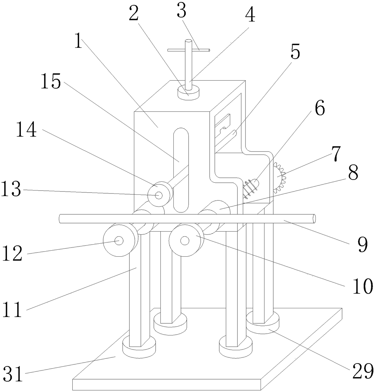
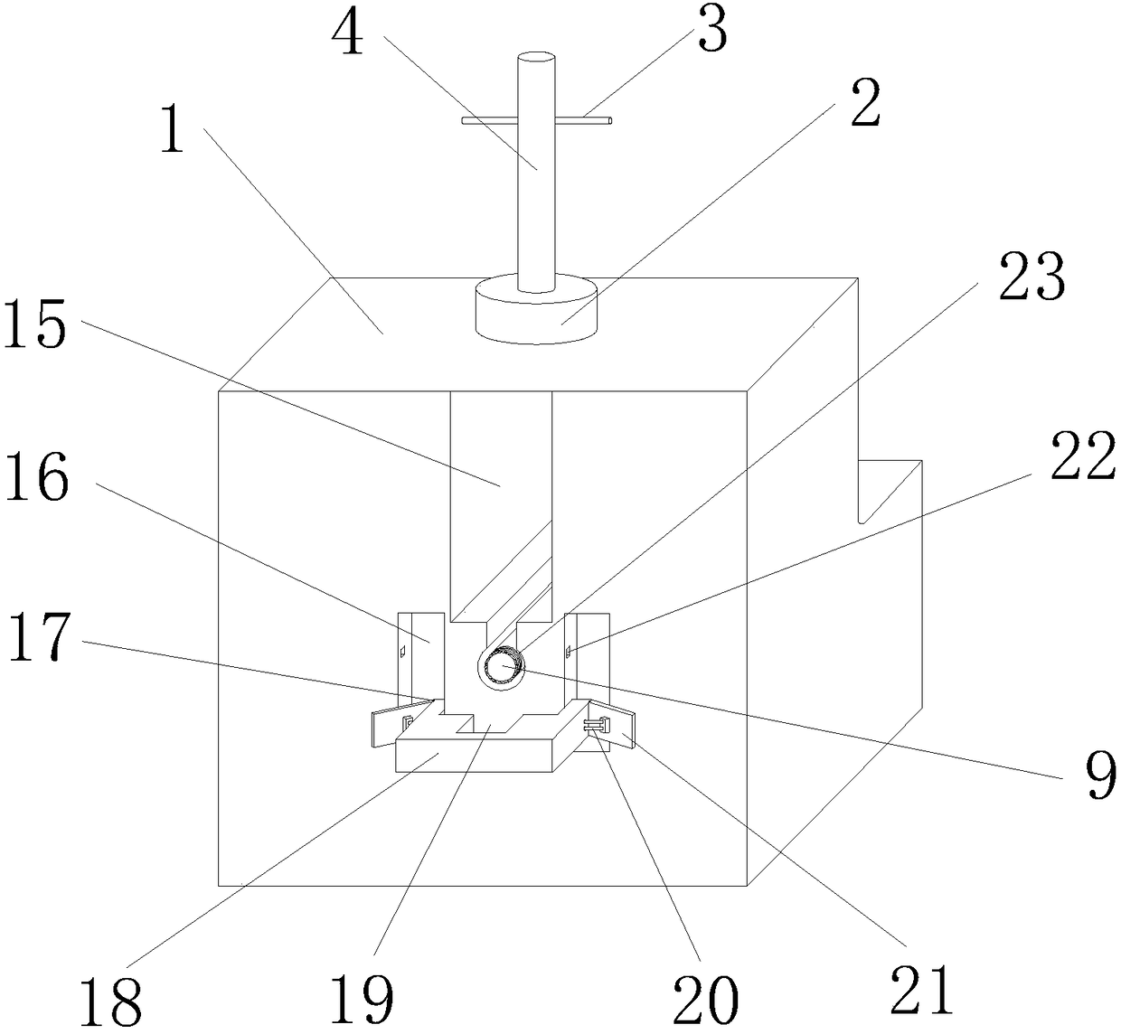
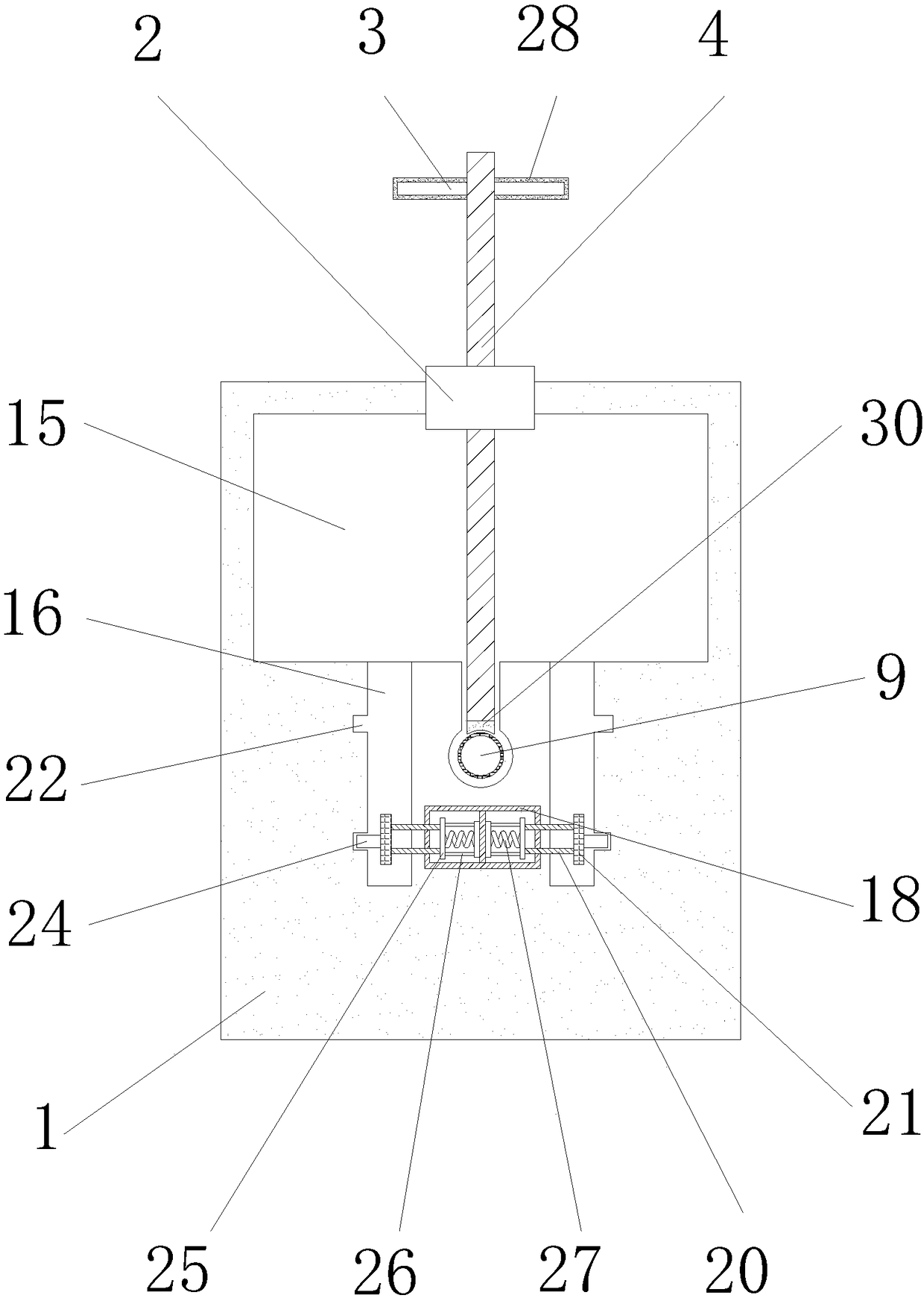
[0017] Below in conjunction with accompanying drawing and embodiment of description, specific embodiment of the present invention is described in further detail:

[0018] see Figure 1-3 , the present invention provides a technical solution: an automatic processing equipment for bathroom water pipes, including a body 1, the body 1 is used to fix the connecting block 2, the bottom end of the body 1 is equipped with a connecting block 2, and the connecting block 2 is used to fix the rotating rod 4 , the bottom end of the connecting block 2 is provided with a rotating rod 4, the rotating rod 4 rotates to fix the water pipe 9, the bottom end of the rotating rod 4 is equipped with a plastic pad 30, and the plastic pad 30 is used to increase the friction between the rotating rod 4 and the water pipe 9 , the top of the outer wall of the rotating rod 4 is equipped with a handle 3, the handle 3 is used to drive the rotating rod 4 to rotate, the outer wall of the handle 3 is equipped wi...


PUM


Abstract

The invention discloses automatic processing equipment for a sanitary water pipe. The automatic processing equipment for the sanitary water pipe comprises a body, wherein a connecting block is mountedat the bottom end of the body; a rotary rod is arranged at the bottom end of the connecting block; the rotary rod penetrates through the connecting block and the body; a cavity is formed in the body;a water pipe is arranged at the bottom end in the cavity; a thread is arranged at the top end of the outer wall of the water pipe; the water pipe is connected to the rotary rod in lap joint; and slots are formed in the left and right sides of the bottom end in the front surface of the body. According to the automatic processing equipment for the sanitary water pipe disclosed by the invention, a clamping plate is pressed, so that a baffle plate squeezes a compression spring in a bump, a locking rod on the clamping plate is locked into the bump to connect a pipe sleeve in the groove to the water pipe oppositely, the water pipe and the pipe sleeve are effectively connected, the problems that the manually mounted pipe sleeve on the water pipe is inconvenient in a time- and labor-wasting manner, and the production efficiency is reduced are solved, and meanwhile, the automatic processing efficiency of the sanitary water pipe is enhanced, and the demand on the market is met.

Description

technical field [0001] The invention relates to the technical field of automatic processing equipment for sanitary water pipes, in particular to automatic processing equipment for sanitary water pipes. Background technique [0002] The workload of the water pipe for bathing is basically to cut the water pipe, install the steel sleeve, assemble the copper core of the nut, tighten the copper core of the nut and clamp the steel sleeve. The existing work of tightening the nut is still in the stage of manual production, such as the patent application number 201520240501.7, It includes a workbench with slide rails, a jacket machine set on the workbench, and nine station claws that are slid on the slide rails in turn. On the left side of the first station claw on the workbench is Cutting device, this patent cannot effectively install the pipe cover on the water pipe, avoiding the inconvenient installation when installing the water pipe and pipe cover manually, and the installation ...

Claims


Application Information

Patent Timeline
Patent Type & Authority Applications(China)
IPC IPC(8): B23P19/00
CPCB23P19/00
Inventor 单筱慧
Owner WUHU HUIYU TRADING CO LTD
Why Eureka
Try Eureka