Anti-clogging device, control method and sewage pump

A control method and anti-clogging technology, which are applied in pump control, components of pumping devices for elastic fluids, pumps, etc., can solve the problems of insignificant impurity treatment effect, burning down the motor of sewage pump, and reducing pump efficiency, etc. Achieve the effect of improving the efficiency of automated processing, reducing the possibility of blockage, and improving work efficiency

Active Publication Date: 2020-08-28
JIANGSU UNIV
View PDF12 Cites 0 Cited by
  • Summary
  • Abstract
  • Description
  • Claims
  • Application Information

AI Technical Summary

Problems solved by technology

Because the transported sewage contains substances that are easy to entangle or deposit and agglomerate, and are not easy to be sucked by the sewage pump, traditional sewage pumps are not easy to pump this kind of sewage, and the entangled substances are easy to cause the sewage pump to block. Once the sewage pump Blockage will lead to poor sewage discharge, and even burn the motor of the sewage pump
At present, the existing sewage pump can reduce the occurrence of impurity clogging by adding a filter screen or a front cutting blade on the pump shaft. There is no detailed impurity treatment plan, and the effect of impurity treatment is not obvious; the existing sewage pump is still Impurities are intercepted through the filter screen, and high-pressure fluid is introduced through the pump outlet to backwash the filter screen, but this method reduces the efficiency of the pump

Method used


Image

  • Anti-clogging device, control method and sewage pump
  • Anti-clogging device, control method and sewage pump
  • Anti-clogging device, control method and sewage pump

Examples


Embodiment approach

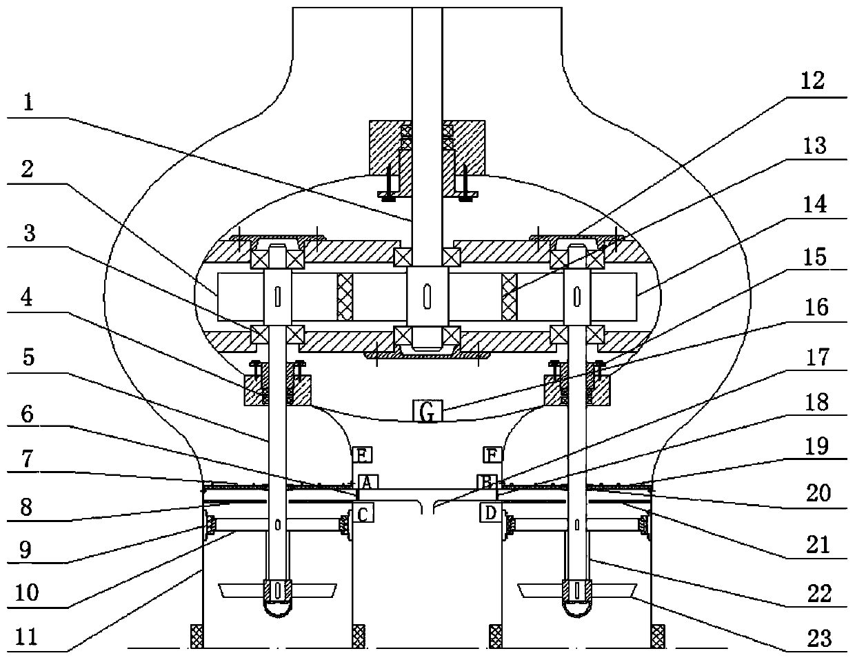
[0037] figure 1 Shown is an embodiment of the anti-clogging device of the present invention. The anti-clogging device includes two water inlet pipes 11, a debris discharge pipe 17, an impeller 23, a motor shaft 1, a filter screen 19, a pressure sensor 7, First valve, second valve, gear clutch and controller.

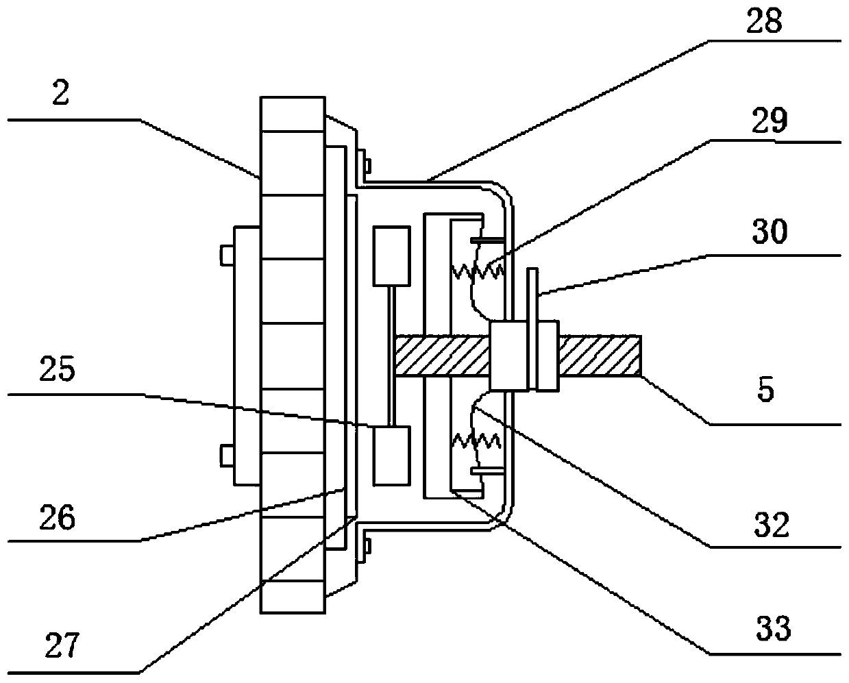
[0038] The water inlet ends of the water inlet pipes 11 are respectively provided with impellers 23, and the water outlet ends of the two water inlet pipes 11 are connected; The gear train connection of the output end of the motor shaft 1. The gear train includes a driving gear and a driven gear; the output end of the motor shaft 1 is provided with a driving gear 13; the driving gear is at least connected with two driven gears; the driven gear is connected to the impeller shaft through a gear clutch 5 connections. Specifically, the driven gear includes a driven gear A2 and a driven gear B14.

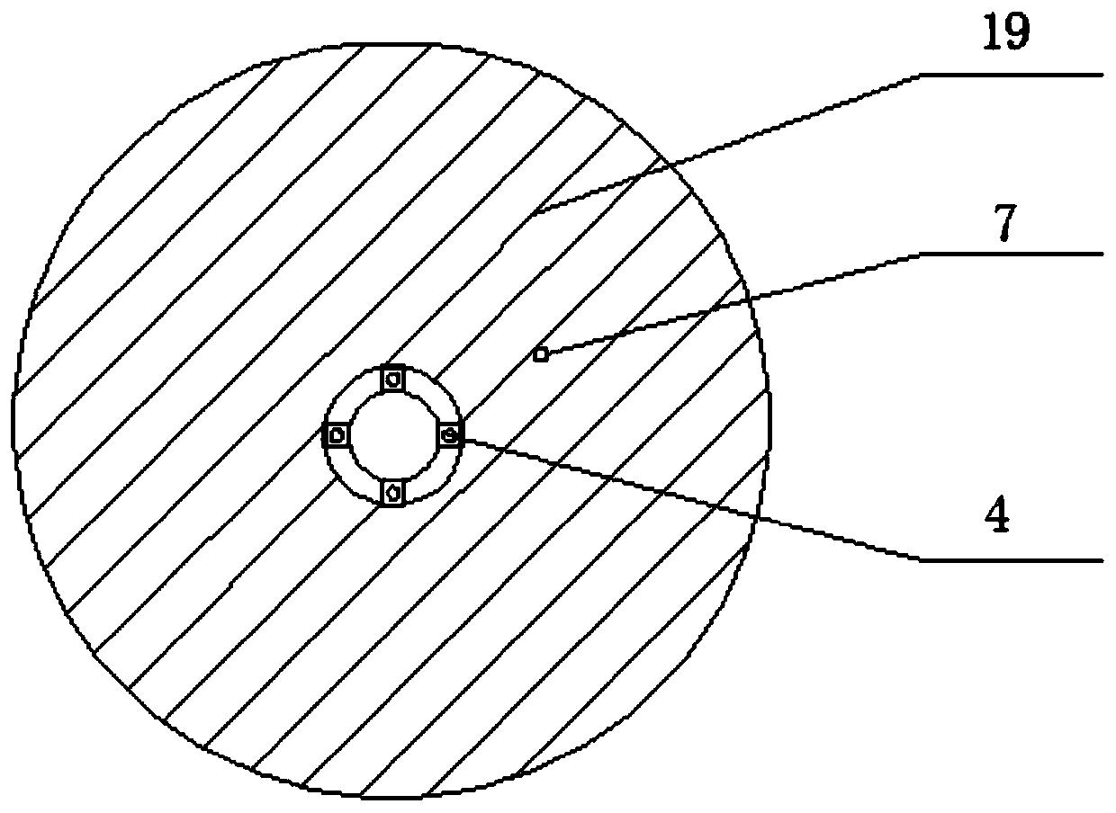
[0039] The filter screen 19 is installed at the water inlet end of the wat...

Embodiment 2

[0060] A sewage pump includes the anti-clogging device described in Embodiment 1, so it has the beneficial effects of Embodiment 1, and will not be repeated here.


PUM


Abstract

The invention provides an anti-blocking device, a control method and a sewage pump. The anti-blocking device comprises at least two water inlet pipes, a sundry discharging pipe, impellers, a motor shaft, filter screens, pressure sensors, first valves, second valves, gear clutches and a controller. The impellers are arranged at the water inlet ends of the water inlet pipes, and the water inlet endsof the water inlet pipes are connected. Each impeller is connected with one end of an impeller shaft, and the other ends of the impeller shafts are connected with a gear train at the output end of the motor shaft through the gear clutches. The filter screens are mounted at the water inlet ends of the water inlet pipes and located behind the impellers. The first valves are arranged between the filter screens and the impellers. The sundry discharging pipe is provided with a water inlet and a water outlet, the water inlet is connected with the positions, between the filter screens and the firstvalves, on the water inlet pipes, and the second valves are arranged at the joints correspondingly. By means of the anti-blocking device, the blocked water inlet pipe can be subjected to back washingthrough water of the water inlet pipe at the normal working end, danger brought by pump body demounting is avoided, the service life of the pump body is prolonged, and therefore the work efficiency ofthe pump is improved.

Description

technical field [0001] The invention belongs to the field of sewage pumps, and relates to an anti-clogging device, a control method and a sewage pump. Background technique [0002] Sewage pumps are usually used to transport sewage, including: urban or rural sewage, liquid containing fibrous impurities, liquid containing granular impurities, etc. Because the transported sewage contains substances that are easy to entangle or deposit and agglomerate, and are not easy to be sucked by the sewage pump, traditional sewage pumps are not easy to pump this kind of sewage, and the entangled substances are easy to cause the sewage pump to block. Once the sewage pump Blockage will lead to poor sewage discharge, and even burn the motor of the sewage pump. At present, the existing sewage pump can reduce the occurrence of impurity clogging by adding a filter screen or a front cutting blade on the pump shaft. There is no detailed impurity treatment plan, and the effect of impurity treatmen...

Claims


Application Information

Patent Timeline
Patent Type & Authority Patents(China)
IPC IPC(8): F04D7/04F04D15/02F04D29/00F04D29/044F04D29/70
CPCF04D7/045F04D15/0245F04D29/007F04D29/044F04D29/708
Inventor 刘栋宋涛康灿刘子凌
Owner JIANGSU UNIV
Why Eureka
Try Eureka