A dynamic magnetic compensation method for a distributed magnetic anomaly detection system

A detection system and magnetic anomaly technology, applied in the field of magnetic anomaly detection, can solve problems affecting the performance of the magnetic anomaly detection system and measurement result errors, and achieve the effects of improving precision, accuracy, and performance

Active Publication Date: 2019-06-11
BEIJING AUTOMATION CONTROL EQUIP INST
View PDF9 Cites 0 Cited by
  • Summary
  • Abstract
  • Description
  • Claims
  • Application Information

AI Technical Summary

Problems solved by technology

However, during the actual flight of the carrier, in addition to the above-mentioned carrier interference magnetic field, there will be other factors that may affect the magnetometer measurement. Therefore, the traditional carrier interference magnetic field model cannot fully describe the real physical process, resulting in large differences in the measurement results. errors, which in turn affect the performance of the magnetic anomaly detection system

Method used


Image

  • A dynamic magnetic compensation method for a distributed magnetic anomaly detection system
  • A dynamic magnetic compensation method for a distributed magnetic anomaly detection system
  • A dynamic magnetic compensation method for a distributed magnetic anomaly detection system

Examples


Embodiment Construction

[0033] The present invention will be further described below in combination with specific embodiments.

[0034] Step 1, establishing an optimized carrier magnetic field compensation model.

[0035] The traditional magnetic field interference model is:

[0036] h m =H o +X p +X i h o +X e h o (1)

[0037] Among them, H m is the magnetometer measured value vector, H o is the true value vector of the geomagnetic field, X p is the constant disturbance magnetic field vector of the carrier, X i is the carrier-induced interference magnetic field parameter matrix, X e is the carrier eddy current interference magnetic field parameter matrix.

[0038] The real magnetic field is:

[0039]

[0040] make

[0041] Among them, x=(x p ,x i ,…) are the parameters of the carrier constant, induction and eddy current interference magnetic field models.

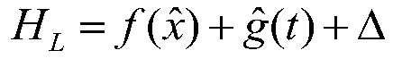
[0042] Considering the non-model parameter error in the actual measurement, a semi-parametric model is introduced to rep...


PUM


Abstract

The invention belongs to the field of magnetic abnormality detection, and specifically discloses a dynamic magnetic compensation method for a distributed magnetic abnormality detection system. The method comprises the steps: building a following optimized carrier magnetic field compensation model, determining a final parameter estimated value (shown in the description) of x and a non-parameter estimated value (shown in the description) of an independent identically distributed random subsample g(t) through a double-stage estimation method, carrying out the dynamic compensation for the carriermagnetic interference, and solving the magnetic field intensity after carrier magnetic compensation. On the one hand, the method enables a carrier interference magnetic field model to accord with thereality in a better way, and improves the accuracy of the model; on the other hand, the method also improves the parameter estimation precision and reduces the measurement error. Meanwhile, the methodimproves the performances of the distributed magnetic abnormality detection system through real-time high-precision dynamic compensation.

Description

technical field [0001] The invention belongs to the field of magnetic anomaly detection, and in particular relates to a dynamic magnetic compensation method for a distributed magnetic anomaly detection system. Background technique [0002] The magnetic anomaly detection system can realize the detection, identification, tracking and positioning of submarines. It has the outstanding characteristics of high submarine positioning accuracy and all-weather application. It can detect magnetic anomalies and accurately locate magnetic anomaly targets in complex sea conditions or complex underwater acoustic environments. Compared with traditional sonar submarine exploration, it has irreplaceable advantages, and has become a key technology for submarine exploration vigorously developed by various military powers in the world. Focusing on the major strategic needs of magnetic anomaly detection, a distributed magnetic anomaly detection system based on a new atomic magnetometer is propose...

Claims


Application Information

Patent Timeline
Patent Type & Authority Patents(China)
IPC IPC(8): G01V3/38G01V13/00
CPCG01V3/38G01V13/00
Inventor 秦杰魏晓虹王春娥王同雷韩文法尚克军
Owner BEIJING AUTOMATION CONTROL EQUIP INST
Why Eureka
Try Eureka