
Blast hole forming structure for cutting blasting of small section roadway

A technology with layout structure and small section, applied in blasting, tunnel, mining equipment and other directions, can solve the problems of large blasting clamping effect, small cutting depth, difficult to meet cutting requirements, etc., to achieve low explosive consumption and drilling. A small number, the effect of which is conducive to throwing

Inactive Publication Date: 2018-05-22
内蒙古康宁爆破有限责任公司
View PDF7 Cites 11 Cited by
  • Summary
  • Abstract
  • Description
  • Claims
  • Application Information

AI Technical Summary

Problems solved by technology

[0004] Due to the small excavation section of the underground engineering, the traditional drilling method generally adopts straight hole blasting, that is, the cutting hole, auxiliary hole and peripheral holes are all drilled along the length of the roadway. Since it is a single free surface operation, the compensation space is small, and the blasting The clamping effect is relatively large, the cutting depth is small, the gravel throwing effect is poor, the amount of ore collapsed is small, the cutting blasting efficiency is low, and it is difficult to meet the cutting requirements

Method used


Image

  • Blast hole forming structure for cutting blasting of small section roadway
  • Blast hole forming structure for cutting blasting of small section roadway

Examples


Embodiment 1

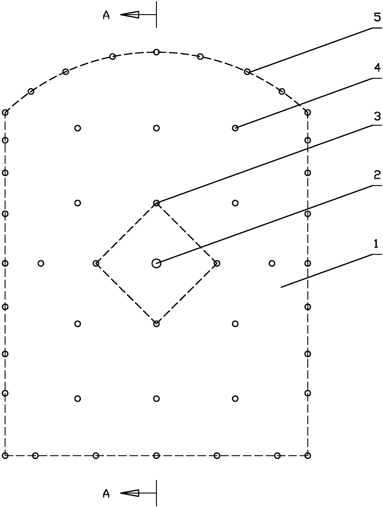
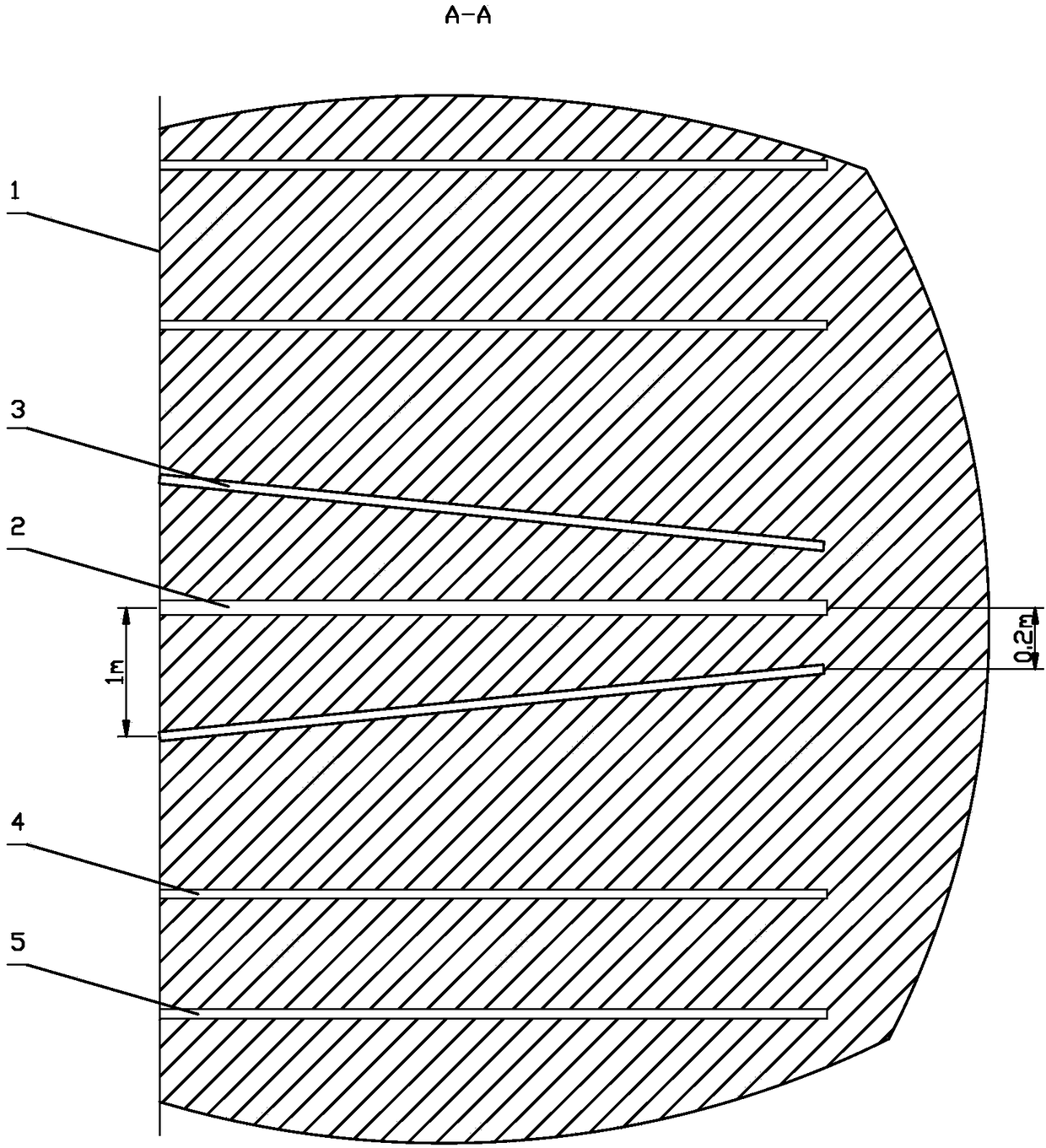
[0018] The blast hole arrangement structure of small-section roadway cutting blasting, which includes a central hole 2 arranged in the center of the roadway driving face 1 and cut holes 3 arranged around the center hole 2, and auxiliary holes 4 are arranged around the cut hole 3, Peripheral holes 5 are arranged on the edge of the design section of the roadway excavation face 1;

[0019] The hole direction of the auxiliary hole 4, the peripheral hole 5 and the central hole 2 is the same as that of the roadway cutting;

[0020] The cut hole 3 gradually converges toward the central hole 2 from the opening to the bottom of the hole.

[0021] When implementing blasting, no explosives are charged in the central hole 2, and explosives are respectively installed in the cutout hole 3, the auxiliary hole 4 and the peripheral hole 5 to implement the blasting.

[0022] The number of holes, the depth of the holes and the pitch of the cut hole 3 are determined according to the size of the ...


PUM


Abstract

The invention discloses a blast hole forming structure for cutting blasting of a small section roadway. The blast hole forming structure comprises a center hole formed in the center of a roadway driving working face and cutting blasting holes formed around the center hole. Auxiliary holes are formed in the peripheries of the cutting blasting holes. Peripheral holes are formed in the edge of the design section of the roadway driving working face. The axial directions of the auxiliary holes and the peripheral holes and the hole direction of the center hole are the same as the cutting blasting driving direction of the roadway. The cutting blasting holes are concentrated gradually towards the center hole from a hole opening to the hole bottom. According to the blast hole forming structure forcutting blasting of the small section roadway, the scheme that the hole bottoms of the cutting blasting holes are concentrated to the position near the center hole, and concentrated charging and detonating together are implemented is adopted, the number of drilled holes is small, the consumption amount of explosive is low, the center hole serves as the auxiliary free surface during charging blasthole blasting and a compensation space of a broken body, the broken body is thrown out advantageously, and the cutting blasting effect is good.

Description

Technical field: [0001] The invention relates to a blast hole layout structure for small-section roadway cutting blasting, and belongs to the technical field of mine blasting. Background technique: [0002] Mine stope and roadway excavation are generally divided into construction forms such as comprehensive mechanized excavation (mechanized excavation) and gun excavation. Comprehensive mechanized excavation uses fully mechanized excavation machines and conveyor belt conveyors to directly transport ore out of the working face. This method requires less manpower and faster construction. Fast, and very safe; however, for rocky areas with high hardness, this method cannot be implemented because the cutter teeth cannot form notches in the roadway section, and blasting must be used. Gun excavation is a construction method in which dotting, drilling, charging, and blasting are carried out on the excavation face, and then the blasted gravel is cleared out of the roadway. [0003] G...

Claims


Application Information

Patent Timeline
Patent Type & Authority Applications(China)
IPC IPC(8): E21D9/00F42D3/04F42D1/00
CPCE21D9/006F42D1/00F42D3/04
Inventor 马保才田辉乔忠利
Owner 内蒙古康宁爆破有限责任公司
Learn More