Plug metal assembly machine capable of integrally pulling and cutting metal strip

A metal strip and assembly machine technology, which is applied to the assembly/disassembly of contact pieces, contact piece manufacturing, electrical components, etc., can solve problems such as low processing efficiency, and achieve the effects of improving processing efficiency, ensuring precision, and ingenious structural design

Inactive Publication Date: 2018-05-18
DONGGUAN UNIV OF TECH
View PDF0 Cites 1 Cited by
  • Summary
  • Abstract
  • Description
  • Claims
  • Application Information

AI Technical Summary

Problems solved by technology

[0002] With the improvement of science and technology, various electronic products emerge in endlessly. Most of the electronics use plugs. image 3 As mentioned, it includes a grooved plug body 21, a vertical circuit board 22 is fixed inside the plug body, the circuit board is connected with a circuit wire 23, and a first pin clamp block 24 and a second pin block are arranged in the plug body. The clamping block 25, the first pin clamping block 24 and the second pin clamping block 25 are provided with grooves that fit in position and cooperate with the metal pins. Therefore, during the processing of this type of plug, the metal pins need to be Pass through and contact the circuit board 22 through the grooves of the first pin holding block and the second pin holding block, and then make it into a whole by welding. In the existing half socket processing process, it is necessary to First cut the metal strip into metal pins of corresponding length specifications, and then put them into the pin insertion device for pin insertion. In this process, most of them are manually operated, and the processing efficiency is low.

Method used


Image

  • Plug metal assembly machine capable of integrally pulling and cutting metal strip
  • Plug metal assembly machine capable of integrally pulling and cutting metal strip
  • Plug metal assembly machine capable of integrally pulling and cutting metal strip

Examples


Embodiment Construction

[0038] In order to enable those skilled in the art to better understand the technical solution of the present invention, the present invention will be described in detail below in conjunction with the accompanying drawings. The description in this part is only exemplary and explanatory, and should not have any limiting effect on the protection scope of the present invention. .

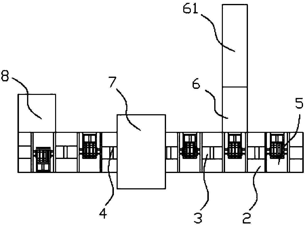
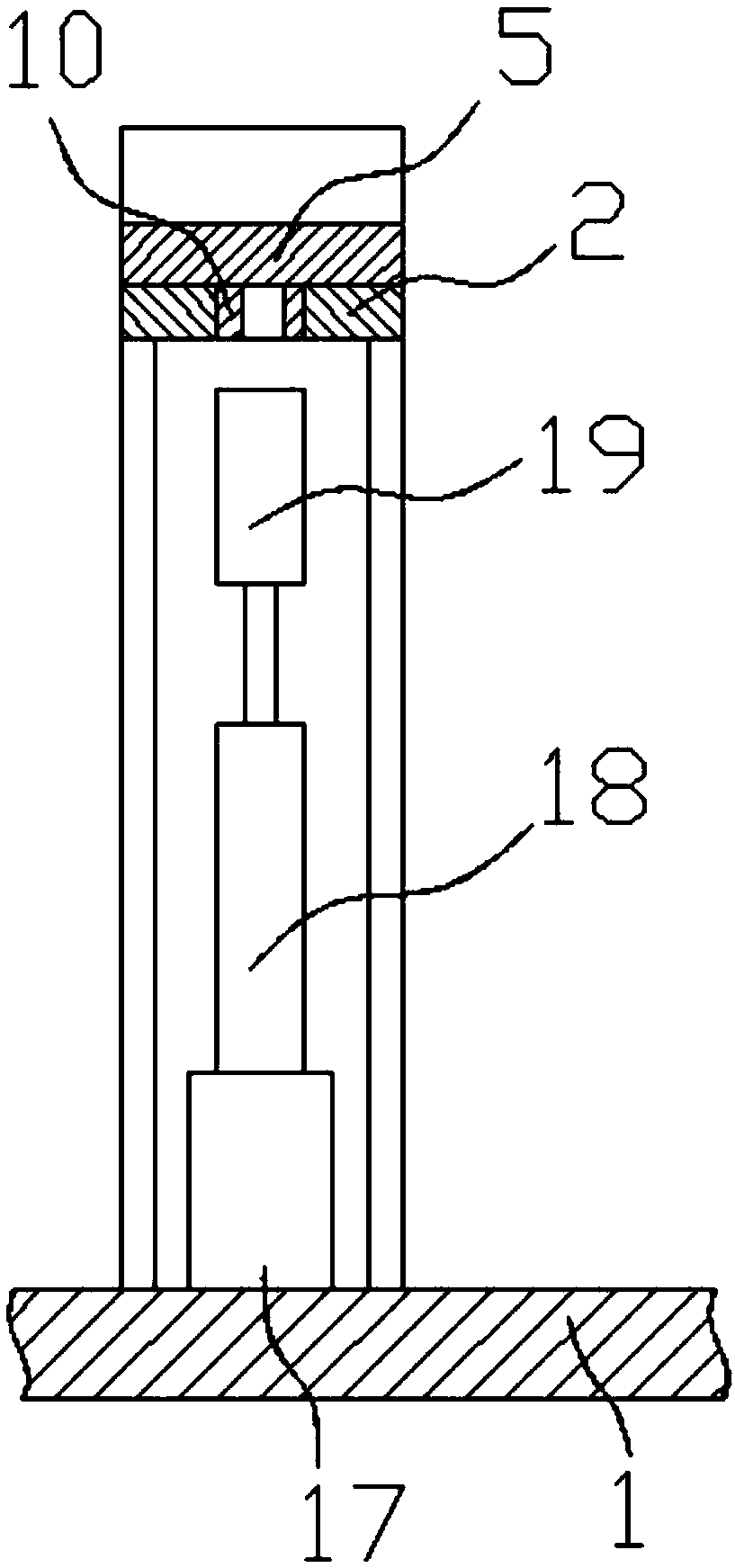
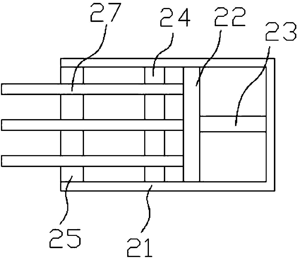
[0039] Such as Figure 1-12 As shown, the specific structure of the present invention is: a plug metal assembly machine that can realize the pulling and cutting of metal strips, which includes a frame 1, and the frame 1 is provided with a conveying mechanism that cooperates with the conveying carrier. The frame 1 described above is sequentially provided with a pin insertion device 6, a welding device 7 and a blanking device 8 that cooperate with the conveying carrier on the conveying mechanism, and the described pin insertion device 6 is equipped with a pulling and cutting device 61, and the described ...


PUM


Abstract

The invention relates to a plug metal assembly machine capable of integrally pulling and cutting a metal strip. The plug metal assembly machine comprises a rack, a transmission mechanism, a pin device, a welding device, a discharging device and a pulling and cutting device, wherein the pulling and cutting device comprises a pull groove seat and a metal roll rotation shaft, a metal roll is arrangedon the metal roll rotation shaft, the groove depth of the pull groove seat is half of the diameter of a metal needle, a cutter device comprises a pulling and cutting seat, a pull motor and a pull lead screw are arranged on the pulling and cutting seat, the pull lead screw is sleeved by a pull movable block, a cutting lifting air cylinder is arranged at a lower part of the pull movable block, a cutting lifting seat is connected with the cutting lifting air cylinder, a vertical cutter is connected with the cutting lifting seat, and an edge of the cutter is a semi-circular notch with the diameter larger than that of the metal needle. By special structure design on the cutter and the pull groove seat, the cutter can complete pulling of the metal strip, the metal strip also can be cut, the pulling and cutting structure is simplified, automatic pulling and cutting is achieved, and the processing efficiency is improved.

Description

technical field [0001] The invention relates to the field of processing equipment for electronic parts, in particular to a plug metal assembly machine capable of pulling and cutting metal strips. Background technique [0002] With the improvement of science and technology, various electronic products emerge in endlessly. Most of the electronics use plugs. image 3 As mentioned, it includes a grooved plug body 21, a vertical circuit board 22 is fixed inside the plug body, the circuit board is connected with a circuit wire 23, and a first pin clamp block 24 and a second pin block are arranged in the plug body. The clamping block 25, the first pin clamping block 24 and the second pin clamping block 25 are provided with grooves that fit in position and cooperate with the metal pins. Therefore, during the processing of this type of plug, the metal pins need to be Pass through and contact the circuit board 22 through the grooves of the first pin holding block and the second pin ho...

Claims


Application Information

Patent Timeline
Patent Type & Authority Applications(China)
IPC IPC(8): H01R43/16H01R43/20H01R43/02
CPCH01R43/16H01R43/0256H01R43/20
Inventor 洪颖邓君
Owner DONGGUAN UNIV OF TECH
Why Eureka
Try Eureka