
Lead bonding method based on rapid local electrodeposition

A wire bonding and electrodeposition technology, used in circuits, electrical components, electrical solid devices, etc., can solve the problems of inability to interconnect wire materials and pads, unreliable wire bonding technology, etc., and achieve fast bonding speed. , Reliable wire bonding, no thermal damage effect

Active Publication Date: 2018-05-18
HARBIN INST OF TECH
View PDF7 Cites 7 Cited by
  • Summary
  • Abstract
  • Description
  • Claims
  • Application Information

AI Technical Summary

Problems solved by technology

[0003] The purpose of the present invention is to solve the unreliable problem of the existing wire bonding technology, and provide a wire bonding method based on rapid local electrodeposition for wire materials (such as carbon-based, carbon-surface-enhanced metal-based, carbon-composite metal-based lead material, etc.) to the pad for wire bonding
The invention can solve the problem that the interconnection between the lead material and the pad cannot be realized by using methods such as thermocompression bonding, ultrasonic bonding, and thermosonic bonding, and realizes rapid selectivity between the lead material and the pad through the local electrodeposition method Interconnection, the whole bonding process does not require heating connection, no thermal damage and mechanical damage, has the advantages of simple process flow, fast bonding speed, suitable for various pad materials, and a wide range of metal types for the connection layer.

Method used

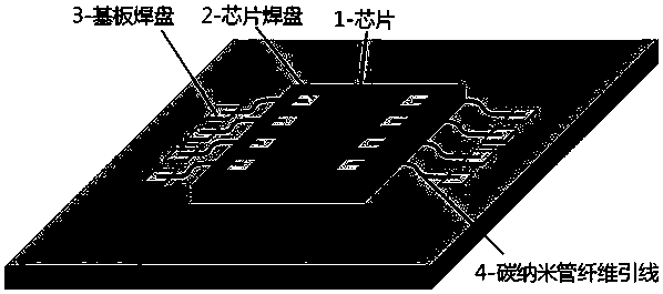

Image

  • Lead bonding method based on rapid local electrodeposition
  • Lead bonding method based on rapid local electrodeposition
  • Lead bonding method based on rapid local electrodeposition

Examples


specific Embodiment approach 1

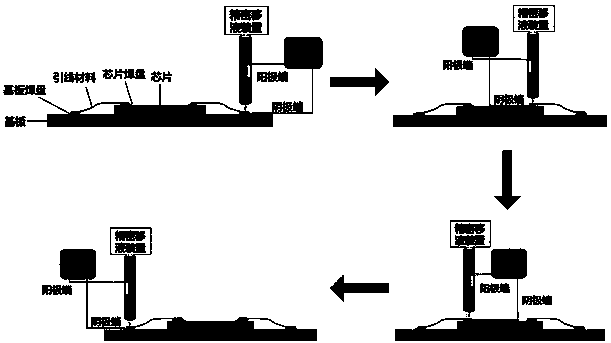
[0027] Specific implementation mode 1: This implementation mode records a wire bonding method based on rapid local electrodeposition. Using the method of local electrodeposition, the new wire material and pad surface that cannot be used in traditional wire bonding technology are realized. Connection, the specific steps of the method are as follows:

[0028] Step 1: Select the wire material to be bonded;

[0029] Step 2: modifying the surface of the lead material selected in step 1, so that the local electrodeposition solution can be well wetted on its surface;

[0030] Step 3: According to the position requirements, place the lead material after surface modification on the surface of the pad through the micro-nano operation platform, ensure that the two ends of the lead are located at the center of the surface of the pad, and ensure that the two ends of the lead are in good contact with the surface of the pad. s contact;

[0031] Step 4: According to the size of the pad, sel...

specific Embodiment approach 2

[0034] Specific embodiment 2: A wire bonding method based on rapid local electrodeposition according to specific embodiment 1, wherein the lead material is a carbon-based lead material, a carbon-surface-enhanced metal-based lead material, or a carbon-composite metal-based lead Material,

[0035] The carbon-based lead material is carbon fiber, carbon nanotube fiber or graphene sheet; the carbon surface-enhanced metal-based lead material is a surface-oriented growth carbon nanotube metal lead, a surface-oriented growth graphene metal lead or a surface coating Graphene-coated metal foil; the carbon composite metal-based lead material is a carbon nanotube composite metal lead or a graphene composite metal lead; the metal is one of copper, nickel, gold or aluminum.

specific Embodiment approach 3

[0036] Specific embodiment three: a wire bonding method based on rapid local electrodeposition described in specific embodiment one, in step two, the surface modification includes surfactant adsorption modification, laser and plasma etching modification After modification, the electrodeposition solution can be well spread on the lead material, and the surface wetting angle of the lead material is less than 10°.

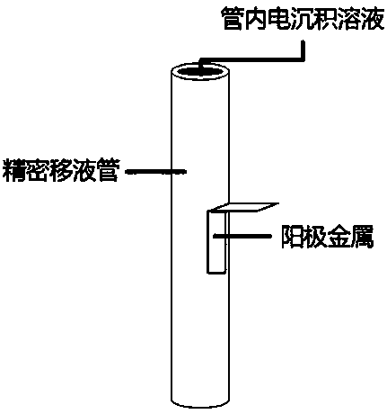
[0037] Embodiment 4: A wire bonding method based on rapid local electrodeposition described in Embodiment 1, step 5 is specifically: the electrodeposition solution is dripped on the micro-nano operating platform through a precision pipette Ensure that the pipette tip is not below the electrodeposition solution liquid level on the surface of the pad, and the electrodeposition solution dripped from the pipette should completely cover the junction of the pad and lead wire, and at the same time ensure that the electrodeposition solution The deposition solution area should...


PUM

PropertyMeasurementUnit
diameteraaaaaaaaaa
thicknessaaaaaaaaaa
widthaaaaaaaaaa

Abstract

The invention relates to a wire bonding method based on rapid local electrodeposition, and belongs to the technical field of lead connection. The method comprises the following steps of selecting a novel lead material to be bonded and modifying the novel lead material; placing the lead material on the surface of a bonding pad through a micro-nano operation platform, ensuring that the lead is in good contact with the surface of the bonding pad; and selecting the caliber of a local electrodeposition precise pipette and the type of an anode metal in the pipette to ensure good contact between an electroplating cathode end probe and the bonding pad; forming a metal coating which completely coats the lead material on the surface of the bonding pad through a local electrodeposition method; and cleaning the entire device after the bonding of the electrodeposition leads on the surface of the bonding pad. Compared with a traditional lead bonding process, the method disclosed by the invention hasthe advantage that reliable lead bonding of the novel lead material can be realized, heating connection is not needed in the whole bonding process, and the whole bonding process is free of thermal damage and mechanical damage. The method is simple in technological process and high in bonding speed, and is suitable for various bonding pad materials and wide in connection layer metal variety selection range.

Description

technical field [0001] The invention belongs to the technical field of lead wire connection, and relates to a method for wire bonding in electronic packaging technology, specifically, a method for realizing bonding of a new type of wire material by using an electrodeposition method, so as to realize the bonding of the new type of wire bonding material and welding Novel wire-bonding method for interconnecting disks in the solid state. Background technique [0002] With the continuous development and innovation of electronic packaging technology, IC integration density is getting higher and higher. The use of traditional metal wires in wire bonding technology has brought about high resistance and electromigration problems, which seriously affect the power density and reliability of electronic devices. Use new high-conductivity and high-reliability lead materials (such as carbon-based, carbon-surface-enhanced metal-based, carbon-composite metal-based lead materials, etc.) to re...

Claims


Application Information

Patent Timeline
Patent Type & Authority Applications(China)
IPC IPC(8): H01L21/60C25D5/02
CPCH01L24/85C25D5/026H01L2224/8591H01L2224/858H01L2224/85H01L2224/49175H01L2224/45565H01L2224/48472H01L2224/48227
Inventor 郑振王春青孔令超刘威
Owner HARBIN INST OF TECH
Learn More