
Optimized design method of broadband digital array radar reception channel

A digital array radar, receiving channel technology, applied in the direction of reflection/re-radiation of radio waves, utilization of re-radiation, measurement devices, etc., can solve the problem of unable to form the desired broadband beam pattern, etc. The effect of reducing the order

Active Publication Date: 2018-05-18
UNIV OF ELECTRONICS SCI & TECH OF CHINA
View PDF7 Cites 5 Cited by
  • Summary
  • Abstract
  • Description
  • Claims
  • Application Information

AI Technical Summary

Problems solved by technology

[0002] Due to the phased array antenna aperture effect and the antenna aperture transit time of the broadband digital array, the desired broadband beam pattern cannot be formed directly by phase weighting. Therefore, a delay-based broadband beamforming method is required

Method used


Image

  • Optimized design method of broadband digital array radar reception channel
  • Optimized design method of broadband digital array radar reception channel
  • Optimized design method of broadband digital array radar reception channel

Examples


Embodiment

[0060] In this embodiment, it is assumed that the WB-DAR receiving channel extraction multiple is M=6, and M is realized by two-stage extraction. 1 = 2 and M 2 = 3, Ripple δ in the passband c =0.0023, stop band ripple δ s =0.003, pass band cut-off frequency ω c =π / M-Δ, Δ>0, stop band start frequency ω s =π / M, the fractional delay interval Δd=0.1, and the delay error is less than 0.001.

[0061] First set the initial coefficients of the filter to all zeros, use the fminimax function to solve the coefficients of the two-stage anti-aliasing filter and the VFD filter from ① to ③ respectively, and evaluate whether the overall frequency response function of the receiving channel meets the requirements. When the overall frequency response function When the characteristics meet the requirements, the corresponding filter order is given in Table 1. Then, take the filter coefficient at this time as the initial coefficient, and then carry out joint optimization solution. If the obtai...


PUM


Abstract

The invention discloses an optimized design method of a broadband digital array radar reception channel. The relative positions of an extraction module and a fractional delay filter of a broadband digital array radar reception channel are changed, an anti-aliasing filter in a back stage extraction structure is prepositioned, a variable fractional delay filter is arranged before the extraction module to obtain an equivalent multistage filter, and thus people can design a target function and constraint conditions to obtain an optimized design according to the transmission band inner ripple waves, stop band inner ripple waves, transmission band cut-off frequency, and stop band cut-off frequency requirements of the equivalent multistage filter. The provided method can effectively reduce the orders of filters and the system complexity and power consumption are reduced therefore.

Description

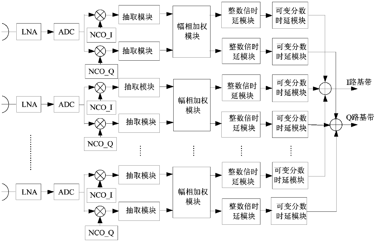
technical field [0001] The invention belongs to the technical field of wideband digital arrays, and in particular relates to an optimal design method of a wideband digital array receiving channel based on delay beamforming. Background technique [0002] Due to the existence of phased array antenna aperture effect and antenna aperture transit time in broadband digital array, the desired broadband beam pattern cannot be formed directly by phase weighting. Therefore, a delay-based broadband beamforming method is required. When using the digital delay method, the conventional wideband digital array (WB-DAR) receiving channel includes N LNA (low noise power amplifier), ADC (digital-to-analog conversion), NCO (digital control oscillator) and amplitude-phase weighting module, And 2N decimation, integer delay and fractional delay modules, where N (N>2) represents the number of channels, and its structure is as follows figure 1 Shown: The input terminal of the LNA is used to inpu...

Claims


Application Information

Patent Timeline
Patent Type & Authority Applications(China)
IPC IPC(8): G01S7/285G01S7/35G01S13/90
CPCG01S7/285G01S7/352G01S13/90
Inventor 钱璐邹林王灿王子晨周云汪学刚
Owner UNIV OF ELECTRONICS SCI & TECH OF CHINA
Learn More