
U-shaped short wheelbase high-speed and high-efficiency multi-wire cutting method

A multi-wire cutting, high-speed technology, applied in the direction of working accessories, fine working devices, stone processing equipment, etc., can solve the problems of affecting cutting stability, low cutting efficiency, easy to cause broken wires, etc., to reduce single-chip wire consumption The effect of reducing cost, improving sheet output efficiency, and shortening the wheelbase of the main roller

Inactive Publication Date: 2018-05-18
HUNAN YUJING MACHINE
View PDF12 Cites 2 Cited by
  • Summary
  • Abstract
  • Description
  • Claims
  • Application Information

AI Technical Summary

Problems solved by technology

[0002] At present, most of the traditional multi-wire cutting machines adopt the L-shaped long-wheelbase cutting method, and its disadvantages are: 1. There are a large number of L-shaped structure guide wheels (17), and the structure of the wire device is complicated, which is easy to cause wire breakage; 2. The cutting method Only the mortar wire cutting method can be used, the line speed is 800-900m / min, the single-knife slicing time of the mortar line is about 8-10 hours, and the cutting efficiency is low; 3. The single-chip wire consumption of the mortar line is about 150m, and the single-chip wire consumption Too large; 4. The mortar wire cutting method needs to prepare mortar before cutting, and the waste mortar needs to be disposed of after cutting, which is both troublesome and not environmentally friendly; 4. The distance between the main rollers is large, and it is easy to form a large wire bow during high-speed cutting, and the wire Many suspended parts of the net are likely to cause wire jumps and affect cutting stability

Method used


Image

  • U-shaped short wheelbase high-speed and high-efficiency multi-wire cutting method
  • U-shaped short wheelbase high-speed and high-efficiency multi-wire cutting method
  • U-shaped short wheelbase high-speed and high-efficiency multi-wire cutting method

Examples


Embodiment

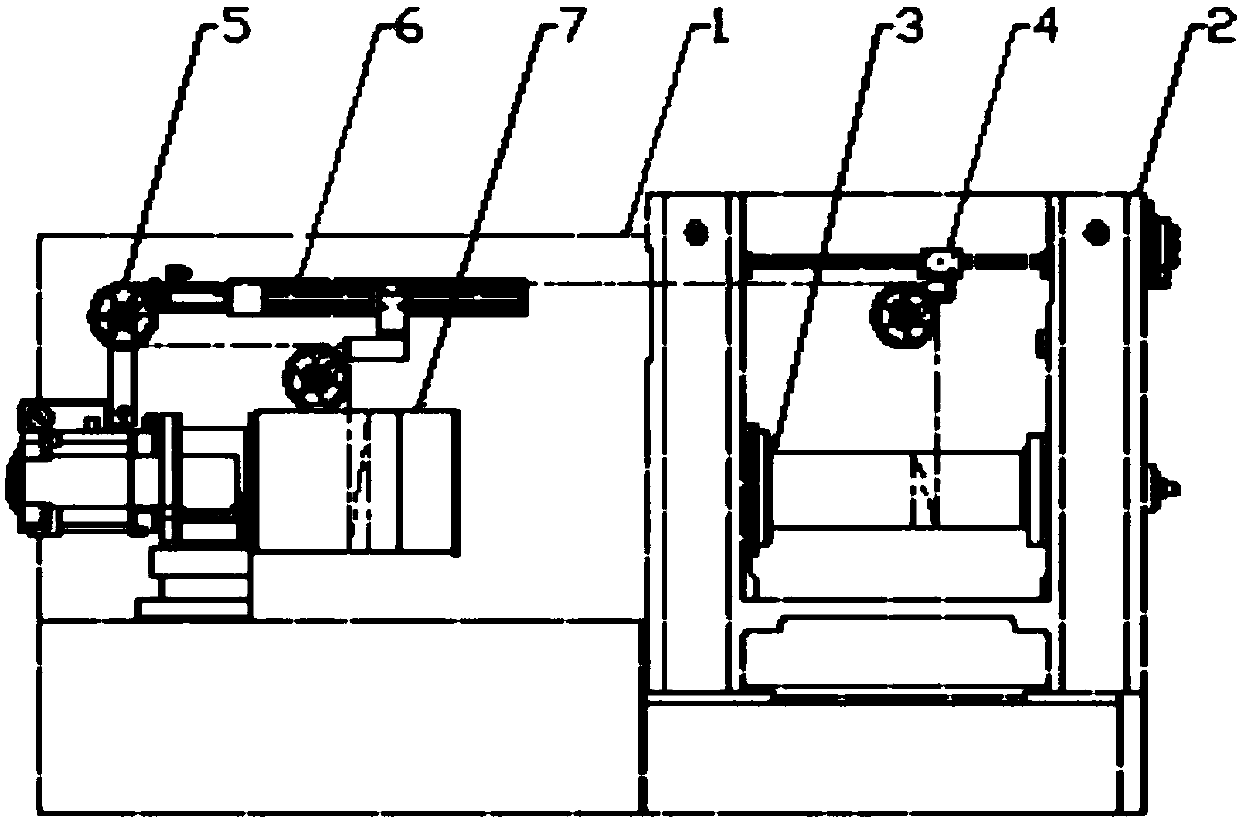
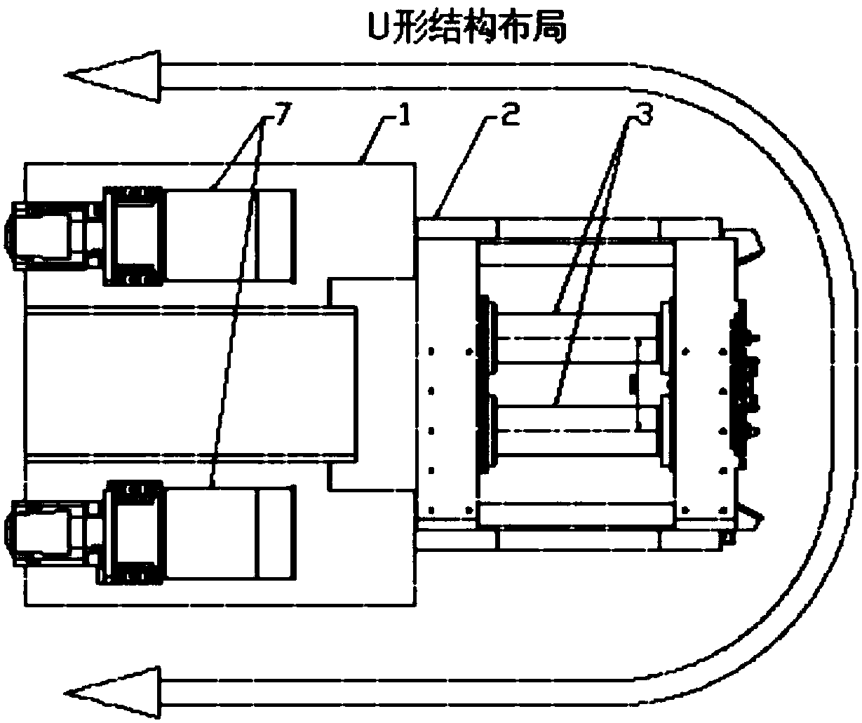
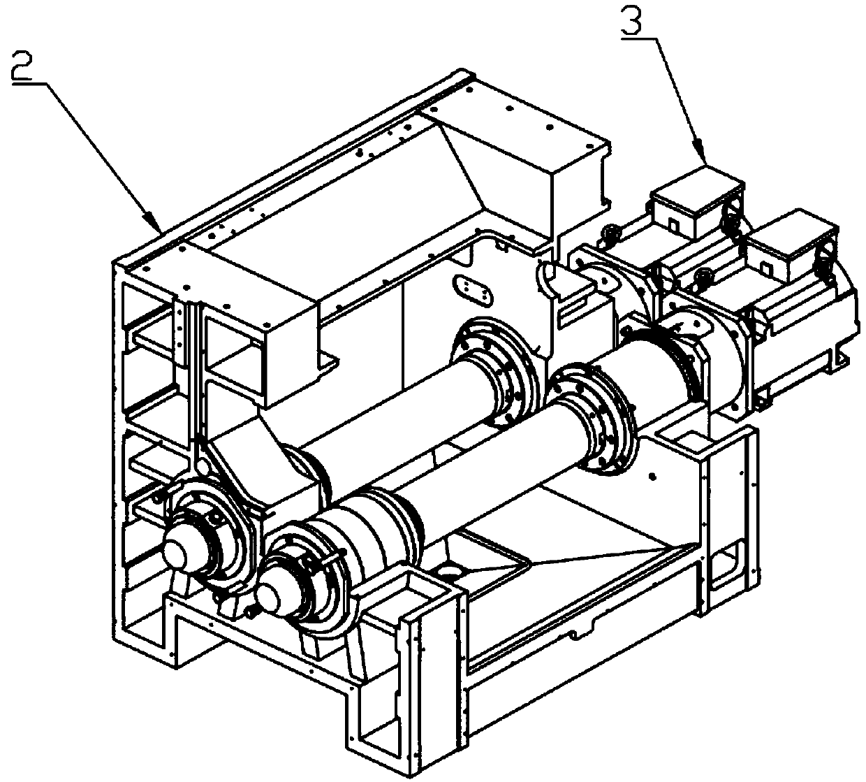
[0021] refer to figure 1 with figure 2 , a U-shaped short wheelbase high-speed and high-efficiency multi-wire cutting method adopts the overall structure of a U-shaped layout, including a frame 1, a cutting room system 2, a spindle system 3, a wire system 4, a tension system 5, and a cable system 6. Take-up / pay-off system 7; the take-up / pay-off system 7, the tension system 5, and the cable arrangement system 6 are symmetrically installed on both sides of the frame 1, and the cutting room system 2 is installed on the front side of the frame 1, The take-up / pay-off system 7, the tension system 5, the wire arrangement system 6, the wire system 4, and the spindle system 3 are sequentially connected through the cutting line, so that the three operation areas of take-up, take-off and cutting are independent of each other, and the overall structure U-shaped layout.

[0022] In this embodiment, the cutting speed is increased to 1800m / min, the structure of the frame 1 and the cutting...


PUM


Abstract

The invention discloses a U-shaped short wheelbase high-speed and high-efficiency multi-wire cutting method. In an overall structure of U-shaped layout, a take-up / pay-off system, a tension system anda wire arrangement system are symmetrically mounted on two sides of a rack respectively; a cutting room system is mounted on the front side of the rack; the take-up / pay-off system, the tension system,the wire arrangement system, a wire guide system and a spindle system are sequentially connected through a cutting wire, so that three operation areas of take-up, pay-off and cutting are independentof each other;the spindle system drives a roller to rotate through direct drive of a drive motor, thereby remarkably reducing influence on the cutting precision caused by the vibration resulting fromrotation of a belt wheel during high-speed cutting;traditional roller diameter as well as the center distance between two rollers are decreased, and the formation of large wire bow is reduced in a high-speed cutting process, thereby guaranteeing the cutting stability. By adopting the cutting method, the slice yield efficiency can be greatly boosted while the cost of single wire slice is lowered, and the slice yield is increased;moreover, blending of cutting fluid is not needed in the cutting of a diamond wire, and the consumable cost and the environmental pollution are reduced.

Description

technical field [0001] The invention relates to a U-shaped short wheelbase high-speed and high-efficiency cutting method for a multi-wire cutting machine. Background technique [0002] At present, most of the traditional multi-wire cutting machines adopt the L-shaped long-wheelbase cutting method, and its disadvantages are: 1. There are a large number of L-shaped structure guide wheels (17), and the structure of the wire device is complicated, which is easy to cause wire breakage; 2. The cutting method Only the mortar wire cutting method can be used, the line speed is 800-900m / min, the single-knife slicing time of the mortar line is about 8-10 hours, and the cutting efficiency is low; 3. The single-chip wire consumption of the mortar line is about 150m, and the single-chip wire consumption Too large; 4. The mortar wire cutting method needs to prepare mortar before cutting, and the waste mortar needs to be disposed of after cutting, which is both troublesome and not environme...

Claims


Application Information

Patent Timeline
IPC IPC(8): B28D5/04B28D7/00
CPCB28D5/045B28D5/0058
Inventor 戴瑜兴杨佳葳尹邦富周小杰
Owner HUNAN YUJING MACHINE
Learn More