
Magnetic ring surface defect detection device and method

A defect detection and magnetic ring technology, which is applied in the direction of measuring devices, optical testing of flaws/defects, and material analysis through optical means, can solve the problems of low automation, heavy workload, and low production efficiency, and achieve enhanced organizational features , high degree of automation, the effect of enhancing image quality

Pending Publication Date: 2018-05-15
FOSHAN POLYTECHNIC
View PDF0 Cites 5 Cited by
  • Summary
  • Abstract
  • Description
  • Claims
  • Application Information

AI Technical Summary

Problems solved by technology

The traditional detection work is usually done manually, which not only has a large workload, but also is often easily affected by the subjective factors of the inspectors, so the efficiency and accuracy of the detection cannot be guaranteed.
If fast speed, high precision, and online automatic detection cannot be realized, the production efficiency of the magnetic ring enterprise will be reduced, and even the economic benefits of the enterprise will be directly affected.
[0003] The traditional magnetic ring detection is manual operation, the detection effect and efficiency mainly depend on the experience of the inspectors, the human influence factors are large, and the degree of automation is low
In addition, the purely manual inspection operation also has the defects of high labor intensity and low production efficiency.

Method used


Image

  • Magnetic ring surface defect detection device and method
  • Magnetic ring surface defect detection device and method
  • Magnetic ring surface defect detection device and method

Examples


Embodiment Construction

[0023] In the description of the present invention, it should be noted that for orientation words, such as the term "center", "horizontal", "longitudinal", "length", "width", "thickness", "upper", "lower" , "Front", "Back", "Left", "Right", "Vertical", "Horizontal", "Top", "Bottom", "Inner", "Outer", "Clockwise", "Counterclockwise " and other indication orientations and positional relationships are based on the orientations or positional relationships shown in the drawings, and are only for the convenience of describing the present invention and simplifying the description, rather than indicating or implying that the device or element referred to must have a specific orientation, or in a specific orientation. The structure and operation should not be construed as limiting the specific protection scope of the present invention.

[0024] In addition, terms such as "first" and "second" are used for descriptive purposes only, and cannot be understood as indicating or implying rela...


PUM


Abstract

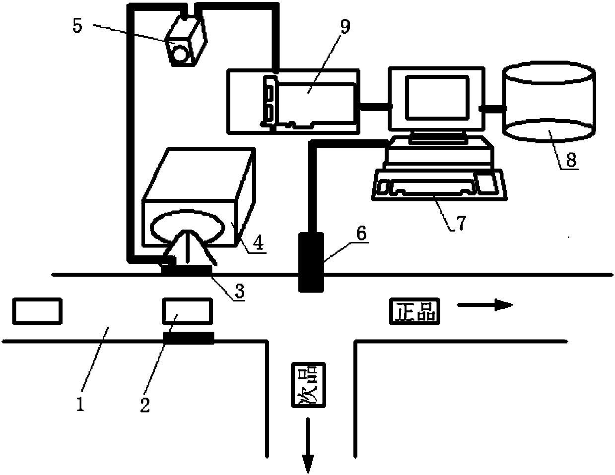
The invention discloses a magnetic ring surface defect detection device, which is characterized by comprising a conveying belt, wherein the conveying belt is used for conveying magnetic rings to be detected; a detection position and a rejection product removal position are arranged in a way of corresponding to the conveying belt; a sensor, a light source and a camera are arranged in a way of corresponding to the detection position; a mechanical hand is arranged in a way of corresponding to the rejection product removal position; a conveying belt driving mechanism, the sensor, the light source,the camera and the mechanical hand are connected with one industrial computer; the industrial computer controls the starting and the stopping of the conveying belt according to signals fed back by the sensor, and judges whether the magnetic rings are qualified products or defect products according to self machine vision software; if the magnetic rings are defect products, the mechanical hand in the next station is driven to act; the defect products are removed; if the products are qualified products, the magnetic rings realize the automatic material turning on the conveying belt; then, the magnetic rings enter the detection region for detecting the other end surface; the detection treatment is performed. The invention also discloses a magnetic ring surface defect detection method.

Description

technical field [0001] The invention relates to the technical field of processing surface defect detection, in particular to a magnetic ring surface detection technology. Background technique [0002] Factors affecting the quality of the magnetic ring mainly include defects such as size and surface scratches. Traditional inspection work is usually done manually, which not only has a large workload, but also is often easily affected by the subjective factors of the inspectors, so the efficiency and accuracy of the inspection cannot be guaranteed. If fast speed, high precision, and online automatic detection cannot be realized, the production efficiency of the magnetic ring enterprise will be reduced, and even the economic benefits of the enterprise will be directly affected. [0003] The traditional magnetic ring detection is manual operation, the detection effect and efficiency mainly depend on the experience of the inspectors, the human influence factors are large, and the...

Claims


Application Information

Patent Timeline
Patent Type & Authority Applications(China)
IPC IPC(8): G01N21/88G01N21/84
CPCG01N21/84G01N21/8851G01N2021/845G01N2021/8887
Inventor 易铭黄远民杨伟杭罗庚兴
Owner FOSHAN POLYTECHNIC
Learn More