Adaptive surface identifying device for optical fiber cable

A technology of optical fiber cable and marking device, applied in the field of hot embossing device, can solve the problems of crushed product quality, accident, and the thickness of the jacket at the embossing place, so as to achieve complete printing content, ensure product quality, and tighten the cable well. Effect

Active Publication Date: 2018-05-15
JIANGSU HENGTONG PHOTOELECTRIC
View PDF7 Cites 2 Cited by
  • Summary
  • Abstract
  • Description
  • Claims
  • Application Information

AI Technical Summary

Problems solved by technology

The disadvantage of using spray printing is that the printed identification content is easily wiped off after the wires and cables are rubbed by transportation bumps, laying and dragging, and the printing content has poor adhesion
The disadvantages of using the single-line embossing form of the printing wheel are: (1) Restricted by factors such as the roundness of the wire and cable and the positioning stability during the production of the wire and cable, it is easy to appear unclear printing; (2) Due to the unilateral impact of the wire and cable sheath The force will cause the thickness of the sheath at the embossed part to become thinner, or even crushed, resulting in product quality accidents; (3) After the actual laying of the wire and cable, if the printed content is laid below, it is easy to cause the phenomenon that the wire and cable model specification is not convenient to check
The above two marking forms have adverse effects on the manufacture, laying-out construction and later maintenance of wires and cables.

Method used


Image

  • Adaptive surface identifying device for optical fiber cable
  • Adaptive surface identifying device for optical fiber cable
  • Adaptive surface identifying device for optical fiber cable

Examples


Embodiment 1

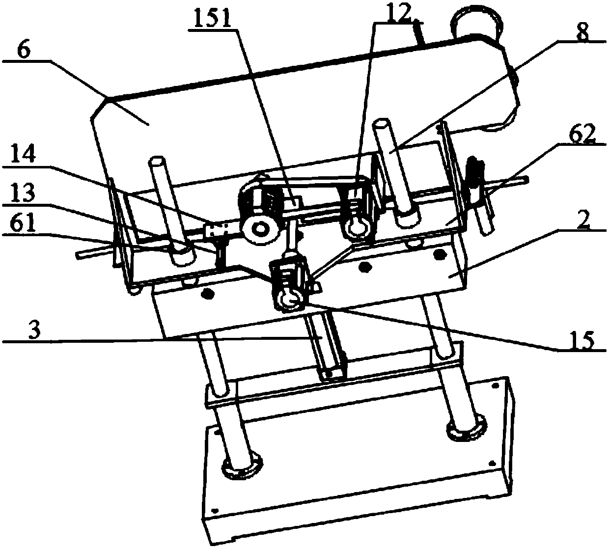
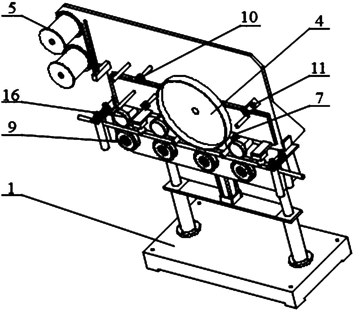
[0021] Embodiment 1: An adaptive surface marking device for optical fiber and cable, comprising: a base 1, a fixed seat 2, a tension adjustment cylinder 3, a heat embossing wheel 4, a ribbon mounting disc 5 wrapped with a ribbon, a lifting plate 6 and a translation Plate 7, two left and right guide shafts 8 fixed on the upper surface of the base 1, the fixed seat 2 is fixed in the middle of the two guide shafts 8, and the front side of the fixed seat 2 is provided with several Supporting the fixed wheel 9, the lifting plate 6 has two guide sleeves 61 arranged left and right, and the guide shaft 8 located above the fixed seat 2 is embedded in the guide sleeve 61 of the lifting plate 6;

[0022] The ribbon mounting disc 5 is installed on the front surface of the lifting plate 6, and a guide wheel 10 fixed to the lifting plate 6 or the flat plate 7 is arranged between the ribbon mounting disc 5 and the hot embossing wheel 4. An air duct 11 for absorbing the ribbon is fixed on the...

Embodiment 2

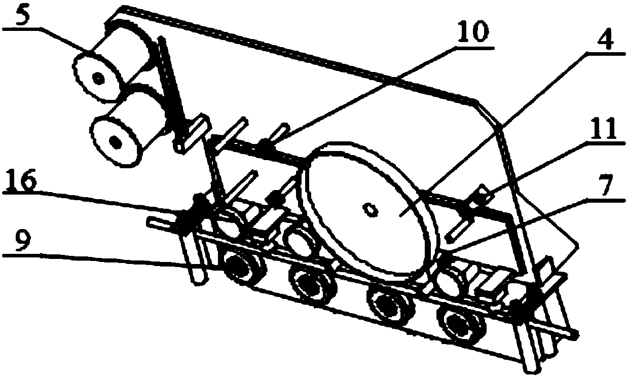
[0027] Embodiment 2: An adaptive surface marking device for optical fiber and cable, including: a base 1, a fixed seat 2, a tension adjustment cylinder 3, a heat embossing wheel 4, a ribbon mounting disc 5 wrapped with a ribbon, a lifting plate 6 and a translation Plate 7, two left and right guide shafts 8 fixed on the upper surface of the base 1, the fixed seat 2 is fixed in the middle of the two guide shafts 8, and the front side of the fixed seat 2 is provided with several Supporting the fixed wheel 9, the lifting plate 6 has two guide sleeves 61 arranged left and right, and the guide shaft 8 located above the fixed seat 2 is embedded in the guide sleeve 61 of the lifting plate 6;

[0028] The ribbon mounting disc 5 is installed on the front surface of the lifting plate 6, and a guide wheel 10 fixed to the lifting plate 6 or the flat plate 7 is arranged between the ribbon mounting disc 5 and the hot embossing wheel 4. An air duct 11 for absorbing the ribbon is fixed on the ...


PUM


Abstract

The invention discloses an adaptive surface identifying device for an optical fiber cable. Two guide shafts which are arranged at the left and right sides are fixed to the upper surface of a pedestalof the adaptive surface identifying device; a fixed base is fixed to the middle parts of the two guide shafts; the front side surface of the fixed base is provided with a plurality of supporting and fixing wheels in the horizontal direction; ink ribbon mounting discs are installed at the front surface of a lifting plate; guide wheels fixed to the lifting plate and a translational plate are arranged between the ink ribbon mounting discs and a hot stamping wheel; the translational plate is positioned in front of the lifting plate; two linear rails which move in the front-and-back direction are arranged in parallel at the upper surface of a base plate of the lifting plate; a tension adjusting cylinder is vertically installed on the pedestal; a cylinder barrel of the tension adjusting cylinderis fixed to the pedestal; and the tail end of a piston rod of the tension adjusting cylinder is connected to the base plate of the lifting plate. The adaptive surface identifying device disclosed bythe invention prevents bruising of the surface of an optical fiber cable protective sleeve, guarantees the product quality and can obtain clear and durable printed word content by means of stamping, and the printed word content is intact, durable and clear.

Description

technical field [0001] The invention relates to the field of thermal embossing devices, in particular to an adaptive surface marking device for optical fiber cables. Background technique [0002] At present, the method for marking the surface of the wire and cable sheath in the domestic market is generally through two methods of inkjet printer printing or single-line embossing of the printing wheel. The disadvantage of using spray printing is that the printed marking content is easily wiped off after the wires and cables are rubbed by transportation bumps, laying dragging and other links, and the printing content has poor adhesion. The disadvantages of using the single-line embossing form of the printing wheel are: (1) Restricted by factors such as the roundness of the wire and cable and the positioning stability during the production of the wire and cable, it is easy to appear unclear printing; (2) Due to the unilateral impact of the wire and cable sheath The force will ca...

Claims


Application Information

Patent Timeline
Patent Type & Authority Applications(China)
IPC IPC(8): B41F17/10B41F33/00
CPCB41F17/10H01B13/341
Inventor 嵇德海轩传吴韦冬何兰珍孙义兴朱芳银李一村李兴进彭朋苇孙瑜滢徐斌朱明
Owner JIANGSU HENGTONG PHOTOELECTRIC
Why Eureka
Try Eureka