Eureka AIR delivers breakthrough ideas for toughest innovation challenges, trusted by R&D personnel around the world.

Rubber sleeve for mandrel of cold rolling coiler

A technology for rubber sleeves and shafts, applied in the field of cold-rolled coilers, can solve problems such as short service life, structural failure, and reduced production efficiency, and achieve the effects of large friction coefficient, good rebound, and reduced head marks

Pending Publication Date: 2018-05-15
北京市城南橡塑技术研究所
View PDF0 Cites 1 Cited by
  • Summary
  • Abstract
  • Description
  • Claims
  • Application Information

AI Technical Summary

Problems solved by technology

[0006] 1. During the process of subdividing the rubber sleeve, a large amount of chemical pollution gas is generated, causing harm and pollution to the operator and the environment, and the rubber sleeve of several hundred kilograms needs to be assembled manually, which is not only inefficient, but also extremely inconvenient Convenience, the structure size can not be effectively guaranteed
[0007] 2. The complete rubber sleeve and the rubber sleeve divided into different numbers of petals are connected by bolts. Due to the limitation of the positioning space and the elastic performance of the rubber material itself, the diameter-increasing sleeve using this connection method is extremely reliable during machine use. Structural failure is prone to occur, and the effect of curling steel coils cannot be guaranteed, which will cause downtime, which not only poses personal safety problems, but also reduces production efficiency and damages equipment
[0008] 3. The rubber sleeve of this structure has a short service life. After the rubber sleeve made of rubber is punched to fix the bolt, the structure of the rubber sleeve itself is damaged, which seriously shortens the service life of the complete rubber sleeve.
[0009] 4. If the polymer plastic flap is used to increase the diameter, it will not have a significant effect on reducing the head print of the steel coil
[0010] 5. The fan-shaped rubber material used for diameter increase generally has not undergone targeted hardness adjustment for slowing down the head mark, so the role of the rubber sleeve to slow down the head mark is not fully utilized during use.

Method used


Image

  • Rubber sleeve for mandrel of cold rolling coiler
  • Rubber sleeve for mandrel of cold rolling coiler

Examples


Embodiment Construction

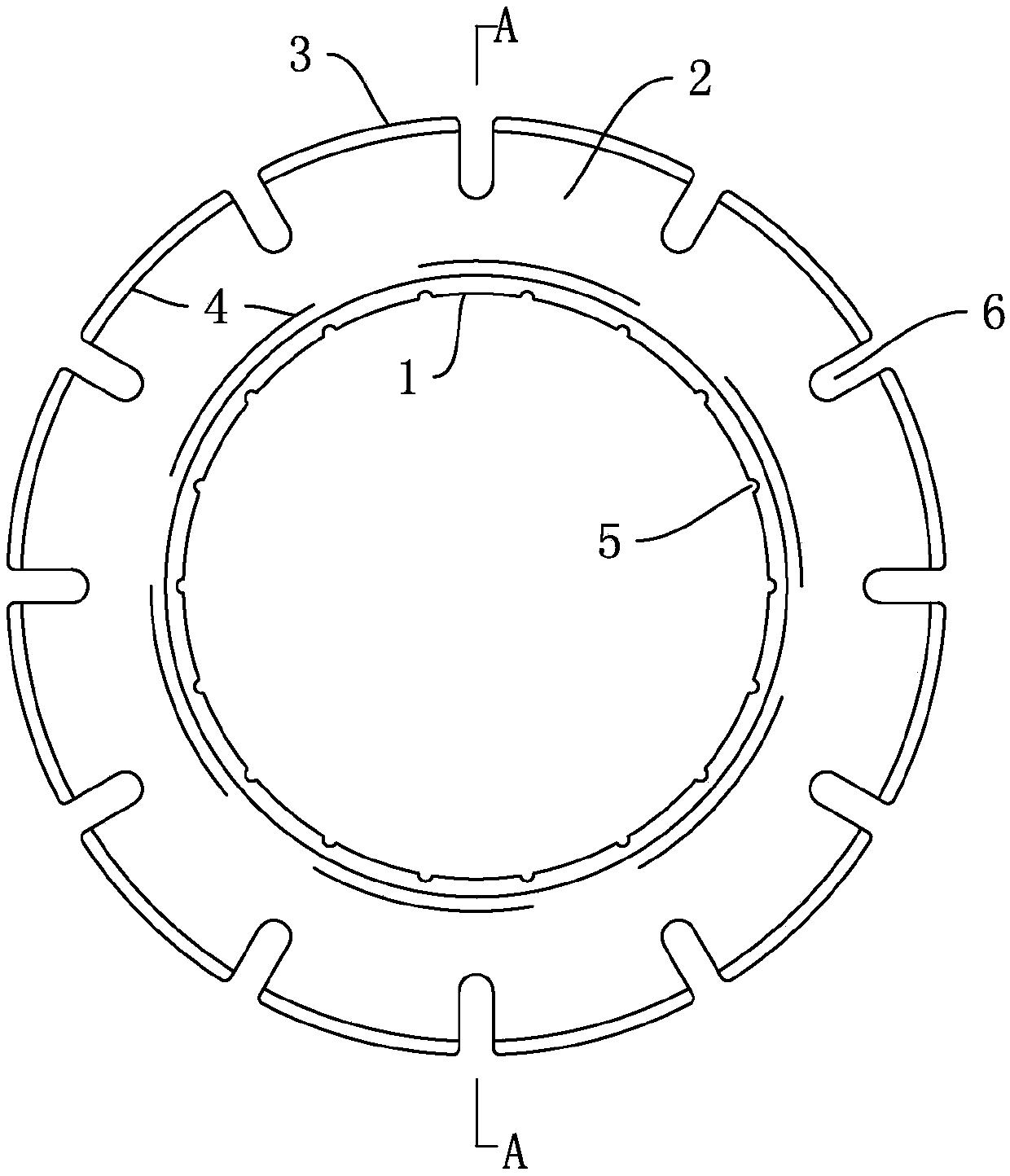
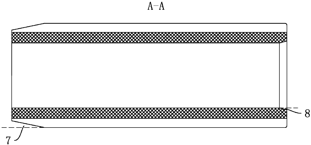
[0033] Such as Figure 1-2 As shown, a rubber sleeve for the mandrel of a cold-rolling and coiling machine is an integral layered composite structure, from the inside to the outside, there are an oil-resistant inner layer 1, a high resilience middle layer 2 and a cut-off head printing outer layer 3 in sequence. The hardness of the oil-resistant inner layer 1, the high resilience middle layer 2 and the cut-off head printing outer layer 3 is the high resilience middle layer 2> Oil resistant inner layer 1> Cut the outer layer of the leading printing 3.

[0034] The adhesive transition layer 4 is used between the oil-resistant inner layer 1 and the high-resilience middle layer 2, and between the high-resilience middle layer 2 and the outer layer 3 of the cutting head printing. The oil-resistant inner layer 1, the high resilience middle layer 2 and the cut-off head printing outer layer 3 are bonded and vulcanized through the adhesive transition layer 4 to form an integral one-time mol...


PUM

PropertyMeasurementUnit
thicknessaaaaaaaaaa

Abstract

The invention discloses a rubber sleeve for a mandrel of a cold rolling coiler. The rubber sleeve is of a layered composite structure, and comprises an oil-proof inner layer, a high-resiliency middlelayer and a subduction zone heading outer layer sequentially from inside to outside. Bonding transitional layers are arranged between the oil-proof inner layer and the high-resiliency middle layer aswell as between the high-resiliency middle layer and the subduction zone heading outer layer. A plurality of inner grooves which are formed in the axial direction of the sleeve and used for increasingthe friction coefficient are evenly distributed on the inner surface of the oil-proof inner layer. A plurality of expansion assisting grooves which are formed in the axial direction of the sleeve areevenly distributed on the outer surface of the subduction zone heading outer layer.

Description

Technical field [0001] The invention relates to the technical field of cold rolling and coiling machines, in particular to a rubber sleeve for a core shaft of a cold rolling and coiling machine. Background technique [0002] The metallurgical iron and steel industry has been a key industry in the reform of the supply-side structure in recent years. The state has continuously issued relevant industry development guidance for the metallurgical iron and steel industry, and planned and batched the elimination, shutdown, and replacement of steel production capacity. In the context of the implementation of the national manufacturing 2025 plan and the vigorous promotion of intelligent manufacturing, in order to meet people’s needs for a better life, people’s requirements for the quality of life are constantly increasing, and higher quality requirements are also put forward for metallurgical steel products, especially It is a cold-rolled product. The quality of the cold-rolled product la...

Claims


Application Information

Patent Timeline
Patent Type & Authority Applications(China)
IPC IPC(8): B21C47/30B21C47/04
CPCB21C47/04B21C47/30
Inventor 黄浩凤成龙胡鹏飞田焕春黄健郭可明殷凯杰魏栓师王继超田丹刘春生蒋彦福
Owner 北京市城南橡塑技术研究所
Why Eureka
Eureka Blog
Learn More