
Bridge erecting machine

A bridge erecting machine and front support technology, which is applied in the direction of erecting/assembling bridges, bridges, bridge construction, etc., can solve problems such as unbalanced force, accidents, asymmetry, etc., achieve large jacking force and prevent asymmetrical force The effect of stability, ensuring balance and uniformity of force

Inactive Publication Date: 2018-05-08
王治民
View PDF0 Cites 0 Cited by
  • Summary
  • Abstract
  • Description
  • Claims
  • Application Information

AI Technical Summary

Problems solved by technology

[0003] For large bridges, two oil cylinders are generally used for synchronous jacking when lifting the girder required for bridge erection. However, when the oil cylinders are under control, instability is prone to occur, and this instability can easily lead to When the beam is lifted, there are phenomena such as unbalanced force. If the unbalanced force is serious, it is easy to cause accidents.
According to statistics, at least one-third of beam lifting accidents are caused by unbalanced and asymmetrical forces. However, the current beam lifting machines generally do not have a structure for monitoring and controlling the lifting of the oil cylinder of the supporting legs.

Method used


Image

  • Bridge erecting machine
  • Bridge erecting machine
  • Bridge erecting machine

Examples


Embodiment Construction

[0019] The following will clearly and completely describe the technical solutions in the embodiments of the present invention with reference to the accompanying drawings in the embodiments of the present invention. Obviously, the described embodiments are only some, not all, embodiments of the present invention. Based on the embodiments of the present invention, all other embodiments obtained by persons of ordinary skill in the art without making creative efforts belong to the protection scope of the present invention.

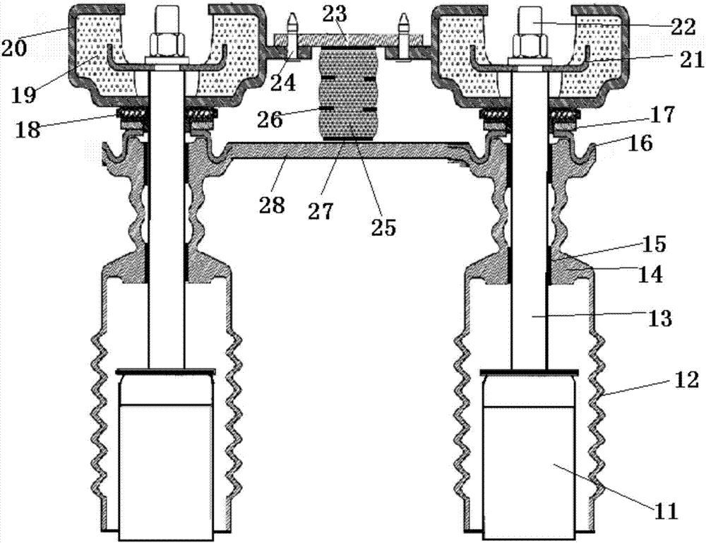
[0020] see Figure 1-2 , the present invention provides a technical solution: a bridge erecting machine, which includes a rear support leg 1, a front support leg 2, an auxiliary support leg 3, a lower guide beam 5, a main beam 6 and a cantilever beam 9, wherein the main The beam 6 is supported on the rear support leg 1 and the front support leg 2, the lower guide beam 5 is supported on the front support leg 2 and the auxiliary support leg 3, and the front side...


PUM


Abstract

The invention discloses a bridge erecting machine. All a rear support leg, a front support leg and an auxiliary support leg are lifted via a dual-cylinder support component; each of the rear support leg, the front support leg and the auxiliary support leg is provided with a correcting component; the correcting components are used for monitoring synchronous balanced motion of the dual-cylinder support components during lifting so as to prevent asymmetric and unbalanced lifting of the dual-cylinder support components during lifting. The bridge erecting machine has the advantages that dual cylinders are used to jack the support legs, great jacking force is provided, and erection of a heavy bridge can be achieved; the dual-cylinder support is provided with the correcting components, it can beensured that a main beam or a guide beam is synchronously jacked during jacking, balance and stress bearing uniformity during jacking can also be ensured, stress bearing asymmetry of the machine during bridge lifting is prevented, and safety and reliability of the machine are guaranteed; the bridge erecting machine provides good operation monitoring and ensures safety.

Description

technical field [0001] The invention relates to a bridge erecting machine, which belongs to the technical field of bridge construction auxiliary equipment. Background technique [0002] The beam lifting machine is a kind of gantry crane specially designed for bridge construction. The beam lifting machine is mainly composed of an assembled main beam, outriggers, crown blocks, etc. The components are connected by pin shafts and high-strength bolts, which is easy to disassemble and transport. Compared with ordinary gantry cranes, it is convenient and quick to install, economical and practical. It is suitable for Frequently mobile road and bridge construction units. The current beam lifting machine is generally equipped with outrigger walking, crane walking and crane lifting equipment, which can realize all-round mechanized actions. It is mainly used to lift the prefabricated beam from the beam manufacturing platform to the beam storage platform. It is hoisted from the beam st...

Claims


Application Information

Patent Timeline
Patent Type & Authority Applications(China)
IPC IPC(8): E01D21/00
CPCE01D21/00
Inventor 王治民
Owner 王治民
Learn More