A device radiator

A heat sink and equipment technology, applied in the construction of electrical equipment components, cooling/ventilation/heating transformation, electrical components, etc., can solve the problems of inconvenient maintenance of electromechanical equipment, affecting the normal operation of electromechanical equipment, poor heat dissipation, etc., to achieve Improve the heat dissipation effect, ensure the normal operation, and ensure the effect of the heat dissipation effect

Inactive Publication Date: 2019-07-02
湖南东峻散热系统有限公司
View PDF5 Cites 0 Cited by
  • Summary
  • Abstract
  • Description
  • Claims
  • Application Information

AI Technical Summary

Problems solved by technology

[0003] Electromechanical equipment will generate heat when it is working. If it cannot dissipate heat effectively, it will affect the normal operation of the electromechanical equipment. The existing electromechanical equipment is usually equipped with ventilation holes or exhaust fans on the installation cabinet of the electromechanical equipment to dissipate heat. The effect is not good. The installation of electromechanical equipment in the installation cabinet is not convenient for maintenance of electromechanical equipment. The existing installation cabinet not only has poor heat dissipation effect, but also is not convenient for maintenance of electromechanical equipment.

Method used


Image

  • A device radiator
  • A device radiator
  • A device radiator

Examples


Embodiment

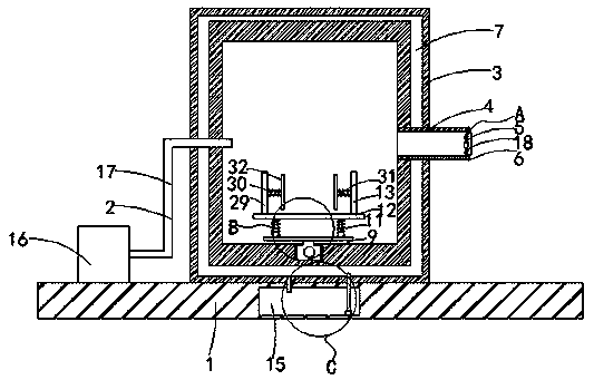
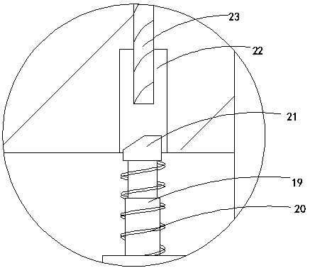
[0018] like Figure 1-5 As shown, an equipment radiator includes a base 1, a cooling device 2 is arranged on the base 1, a cabinet 3 is arranged on the base 1, the side wall of the cabinet 3 is connected with the cooling device 2, and the side wall of the cabinet 3 is An exhaust pipe 4 is provided, and the exhaust pipe 4 is arranged on the side wall of one end of the cabinet 3 away from the refrigeration device 2. An air suction device 5 is arranged in the exhaust pipe 4, and the air suction device 5 is arranged at a distance from the exhaust pipe 4. In one end of the cabinet 3, the top surface and the bottom of the exhaust pipe 4 are provided with a control mechanism 6, and the control mechanism 6 is cooperatively connected with the suction device 5. The cabinet 3 is provided with a cooling channel 7, and the bottom of the cabinet 3 is provided with a cooling channel 7. There is a sliding mechanism 9, the upper end of the sliding mechanism 9 is provided with a first supportin...


PUM


Abstract

The invention belongs to the technical field of electromechanical devices, and particularly relates to an equipment heat radiator, which comprises a base. A refrigerating device is arranged on the base; a cabinet is arranged on the base; a side wall of the cabinet is connected with the refrigerating device; an exhaust pipe is arranged on the side wall of the cabinet, and is arranged on the side wall of one end, far away from the refrigerating device, of the cabinet; a suction device is arranged in the exhaust pipe and is arranged in one end, far away from the cabinet, of the exhaust pipe; control mechanisms are arranged on a top surface and the bottom part of the exhaust pipe, and are connected with the suction device in a matching way; a cooling channel is arranged in the cabinet; a sliding mechanism is arranged on the bottom part of the cabinet; a first support plate is arranged on the upper end of the sliding mechanism; a plurality of buffer devices are arranged on the first supportplate; a second support plate is arranged on the upper ends of the buffer devices; two fixing devices are arranged on the second support plate; an opening is formed in a side wall of the front end ofthe cabinet. The equipment heat radiator provided by the invention has the advantages that not only can a heat radiation effect of an electromechanical device be effectively improved, but also the electromechanical device can be conveniently overhauled.

Description

technical field [0001] The invention belongs to the technical field of electromechanical equipment, and in particular relates to an equipment radiator. Background technique [0002] Equipment is usually a general term for material materials such as machinery, devices and facilities that people need in production and life. Electromechanical equipment is equipment that applies mechanical and electronic technology, and the so-called mechanical equipment is the most important mechanical and electrical equipment. Components, with the continuous improvement of people's living standards, people have more and more needs for electromechanical equipment in their daily life, from transportation to various household appliances, computers, printers, etc. have become indispensable electromechanical products in people's lives . Advanced electromechanical equipment can not only greatly improve labor productivity, reduce labor intensity, improve production environment, and complete tasks th...

Claims


Application Information

Patent Timeline
Patent Type & Authority Patents(China)
IPC IPC(8): H05K7/20
CPCH05K7/20136H05K7/20218
Inventor 文萁
Owner 湖南东峻散热系统有限公司
Why Eureka
Try Eureka