
Motor axial conducted emission test system and method for electric drive system of electric vehicle

An electric drive system, electric vehicle technology, applied in motor generator testing, testing electrical devices in transportation, measuring electricity, etc., can solve problems such as electromagnetic radiation, lack of scientific testing evaluation methods and specifications, and achieve precise control. Effect

Pending Publication Date: 2018-05-04
CHINA AUTOMOTIVE TECH & RES CENT
View PDF0 Cites 6 Cited by
  • Summary
  • Abstract
  • Description
  • Claims
  • Application Information

AI Technical Summary

Problems solved by technology

With the application of PWM frequency conversion technology in the motor drive system and the limitation of the motor manufacturing process, the electromagnetic compatibility problem caused by the motor has gradually been paid attention to. The main reason is that there is a high-frequency common-mode voltage in the PWM drive motor system. The mold voltage will induce a higher on-axis interference voltage (shaft voltage) on the motor shaft and form an interference current (shaft current) through the ground loop. This interference current passes through the inverter-cable-motor parasitic capacitance-motor shaft / Motor ground wire - system ground wire - main power supply - rectifier - inverter path to propagate, this process will cause electromagnetic radiation problems and electromagnetic compatibility problems of other equipment in the electrical circuit caused by conduction
Nowadays, the EMC problem caused by the voltage and current on the motor shaft has attracted more and more attention in the field of automotive EMC, but there is a lack of corresponding scientific testing and evaluation methods and specifications.

Method used


Image

  • Motor axial conducted emission test system and method for electric drive system of electric vehicle

Examples


Embodiment Construction

[0028] It should be noted that, in the case of no conflict, the embodiments of the present invention and the features in the embodiments can be combined with each other.

[0029] In describing the present invention, it should be understood that the terms "center", "longitudinal", "transverse", "upper", "lower", "front", "rear", "left", "right", " The orientations or positional relationships indicated by "vertical", "horizontal", "top", "bottom", "inner" and "outer" are based on the orientations or positional relationships shown in the drawings, and are only for the convenience of describing the present invention and Simplified descriptions, rather than indicating or implying that the device or element referred to must have a particular orientation, be constructed and operate in a particular orientation, and thus should not be construed as limiting the invention. In addition, the terms "first", "second", etc. are used for descriptive purposes only, and should not be understood ...


PUM


Abstract

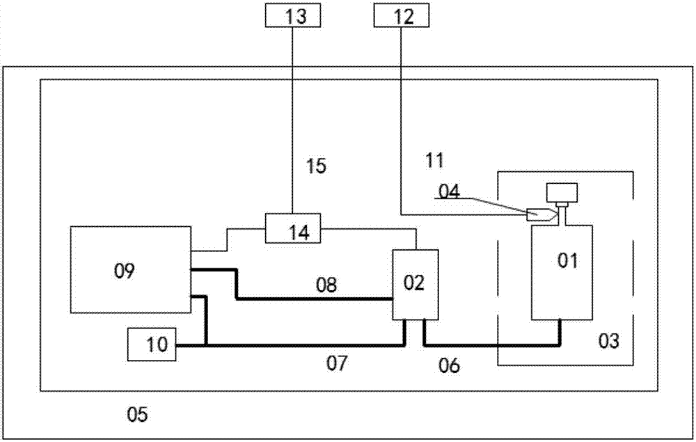
The invention provides a motor axial conducted emission test system and method for an electric drive system of an electric vehicle. The system comprises an electromagnetic environment simulator, a test platform, a signal receiving and processing device and a monitoring device; the electromagnetic environment simulator comprises a high-tension battery pack, a vehicular battery, a motor controller and a motor under test; the test platform is connected with the motor under test; the signal receiving and processing device comprises a receiver and a voltage probe; the monitoring device comprises amonitoring computer and a photoelectric conversion module; the monitoring computer is connected with the motor controller and the high-tension battery pack through the photoelectric conversion module.The system provided herein allows motor axial conducted emission to be measured under loading condition; loaded speed and torque can be precisely controlled; vehicle actual condition and complex electromagnetic environment are simulated, and axial conducted disturbing signals under loading under nearly actual condition are also simulated; reliable data are provided to solve the electromagnetic compatibility issue caused by axial conducted emission of the electric drive system.

Description

technical field [0001] The invention belongs to the technical field of electromagnetic compatibility testing, and in particular relates to a testing system and method for axial conduction emission testing of an electric drive system motor of an electric vehicle. Background technique [0002] The electric drive power system mainly includes two parts: the motor controller and the motor. Nowadays, motor controllers all use PWM frequency conversion control technology, which has its unique advantages, but the electromagnetic compatibility problems it brings are inevitable. The electric drive system has become the main problem of electromagnetic compatibility of new energy vehicles. [0003] In terms of domestic and even international electric vehicle electromagnetic compatibility, the main test targets are the radiated emission of the system and the conducted emission from the low-voltage control line and the DC bus. With the application of PWM frequency conversion technology i...

Claims


Application Information

Patent Timeline
IPC IPC(8): G01R31/00G01R31/34
CPCG01R31/001G01R31/006G01R31/34
Inventor 陈希琛王传琪丁一夫柳海明张旭吴在园马俊杰王云
Owner CHINA AUTOMOTIVE TECH & RES CENT
Learn More