A Jiqun automatic continuous coating process
An extremely group and coating technology, which is applied in the field of extremely automatic continuous coating process, can solve the problems of cumbersome process, low coating efficiency, poor coating quality, etc., and achieve the effect of good effect, simple structure and improved efficiency
- Summary
- Abstract
- Description
- Claims
- Application Information
AI Technical Summary
Problems solved by technology
Method used
Image

Examples
Embodiment 1
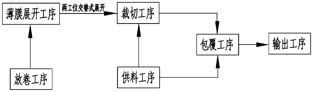
[0072] Such as figure 1 , figure 2 , image 3 , Figure 4 , Figure 5 , Figure 6 , Figure 7 , Figure 8 , Figure 9 and Figure 10 As shown, a Jiqun automated continuous coating process includes the following production steps:
[0073] Step 1, the feeding process, the conveyor belt transports the electrode group to be coated to the feeding station, and the lifting mechanism 12 lifts the electrode group at the feeding station to the coating station;
[0074] Step 2, the unwinding process, unwinding the reel film on the first unwinding station, and the limit mechanism at the first unwinding station limits the end of the unrolled film;
[0075] Step 3, the film unfolding process, the adsorption mechanism 24 adsorbs and fixes the end of the film at the first unwinding station described in step 2, and after the adsorption and fixation is completed, it is driven by the traction mechanism 25 along the guide mechanism 21 Move to unwind the film at the first unwinding stat...
Embodiment 2
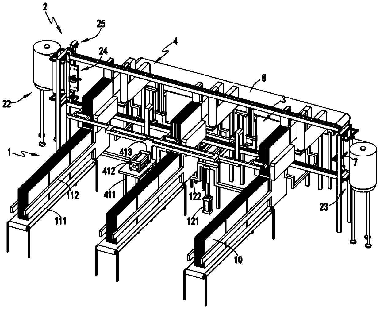
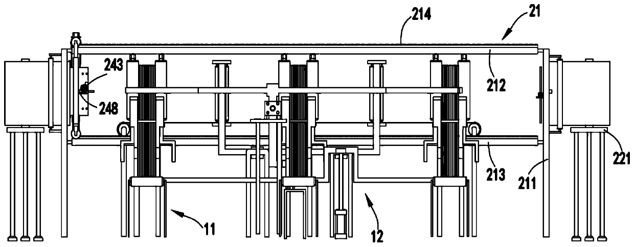
[0089] Such as figure 1 , figure 2 , image 3 , Figure 4 , Figure 5 , Figure 6 , Figure 7 , Figure 8 , Figure 9 and Figure 10 As shown, an automatic continuous coating system for pole groups includes a feeding device 1, and the feeding device 1 includes a horizontal conveying mechanism 11 for horizontally and continuously conveying the pole groups 10 and a lifting mechanism for lifting the pole groups 10. Agency 12;
[0090] Film unwinding device 2, described film unwinding device 2 comprises guiding mechanism 21, the first unwinding mechanism 22 and the second unwinding mechanism 23 that are respectively arranged on guiding mechanism 21 two ends, are used for first unwinding mechanism 22 and The end of the roll film on the second unwinding mechanism 23 is adsorbed and fixed by adsorption mechanism 24 and the traction mechanism 25 for driving the adsorption mechanism 24 and the end of the film to move along the guide mechanism 21;
[0091] Cutting device 3, d...
Embodiment 3
[0115] Such as figure 1 , figure 2 , image 3 , Figure 4 , Figure 5 , Figure 6 , Figure 7 , Figure 8 , Figure 9 and Figure 10 As shown, the parts that are the same as or corresponding to those in the second embodiment are marked with the corresponding reference numerals in the second embodiment. For the sake of simplicity, only the differences from the second embodiment will be described below. The difference between the third embodiment and the second embodiment is that further, the cutting mechanism 31 includes a sliding seat 311, a cutting assembly a312 and a cutting assembly b313 which are slidably arranged on the sliding seat 311 and symmetrically arranged front and rear;
[0116] The cutting assembly a312 includes a slider a3121 that cooperates with the guide rod b3111 on the sliding seat 311 to slide, a connecting frame a3122 that is fixedly connected with the sliding block a3121, a mounting frame a3123 that is arranged at the end of the connecting frame a...
PUM
 Abstract
Description
Claims
Application Information
 - R&D
- Intellectual Property
- Life Sciences
- Materials
- Tech Scout
- Unparalleled Data Quality
- Higher Quality Content
- 60% Fewer Hallucinations
Browse by: Latest US Patents, China's latest patents, Technical Efficacy Thesaurus, Application Domain, Technology Topic, Popular Technical Reports.
© 2025 PatSnap. All rights reserved.Legal|Privacy policy|Modern Slavery Act Transparency Statement|Sitemap|About US| Contact US: help@patsnap.com