
Dust removal respirator

A respirator and liquid container technology, which is applied in the field of air filtration and purification equipment, can solve the problems of frequent replacement, laborious breathing, and short service time of the filter layer, and achieve the effect of increasing the dust removal effect.

Inactive Publication Date: 2018-05-01
尚元奎
View PDF5 Cites 0 Cited by
  • Summary
  • Abstract
  • Description
  • Claims
  • Application Information

AI Technical Summary

Problems solved by technology

[0004] There are two types of isolation masks: one uses a long tube to connect the respirator to a centralized source of fresh air; the other connects the respirator to an air bottle carried by the user; these two isolation masks are expensive and use Very inconvenient and cannot be widely used in labor production
[0005] Filter masks are divided into two categories: one is self-priming filter masks, that is, a filter layer is set inside the mask. This kind of mask has a large breathing resistance. The effective use time of the inner filter layer is very short, it is easy to be blocked, and needs to be replaced frequently; the other is the air-supply filter mask, the filter layer is set inside the mask, and the air supply device continuously supplies air to the mask. , but failed to solve the problem of short usage time of the filter layer
[0006] In order to overcome the above-mentioned defects, the inventor of the present application once provided a new air-supply respirator, which is recorded in the application number 201620289619.3 Chinese patent "An electric air-supply dust-proof respirator"; however, the respirator is in use During the process, due to the heating problem of the fan, the temperature of the air output by the respirator is relatively high, and users are prone to stuffiness in summer

Method used


Image

  • Dust removal respirator
  • Dust removal respirator
  • Dust removal respirator

Examples


Embodiment 1

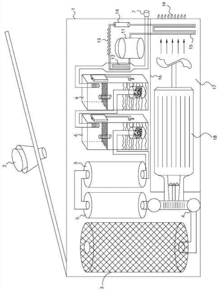
[0024] Such as figure 1 Shown, the dust-removing respirator of the present embodiment comprises:

[0025] Box 1, the box cover of box 1 is provided with a dust collector 2; during normal use, the box cover is closed, air enters box 1 through the dust collector 2, and the dust collector 2 initially removes dust from the air;

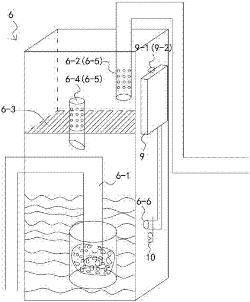
[0026] Air filter cover 3, the first blower fan 4, activated carbon canister 5 and liquid container 6; Air filter cover 3, the first blower fan 4, activated carbon canister 5 and liquid container 6 are connected to form a closed air passage by pipeline, and air filter cover 3 has The inner and outer filter screens are used to remove dust from the air; the first fan 4 drives the outside air from the air filter cover 3 into the activated carbon tank 5 and the liquid container 6, and finally is discharged from the gas outlet 7 at the end of the air channel, and the gas outlet 7 is used to connect Such as image 3 breathing mask 8 as shown;

[0027] The qu...


PUM


Abstract

The invention discloses a dust removal respirator. The dust removal respirator comprises a box body, and an air filtering casing, a first fan, an activated carbon tank, a liquid container and an air conditioner which are mounted in the box body; the air filtering casing, the first fan, the activated carbon tank and the liquid container communicate with one another through a pipeline to form a closed air channel; the first fan drives external air to enter the activated carbon tank and the liquid container from the air filtering casting, and finally, the air is exhausted from an air outlet of the tail end of the air channel; the air outlet is connected with a respirator; the liquid container stores clean water, acidic solution, alkaline water or the like; and the air conditioner cools the air which flows through the air channel. According to the dust removal respirator disclosed by the invention, the first fan is utilized to convey air to a user actively; and the air is subjected to dustremoving, odour removing, wetting and vaporizing cooling treatment through the air filtering casing, the activated carbon tank, the liquid container and the sponge, so that the user can breathe wet,cool and fresh air even in a poor dust pollution environment.

Description

technical field [0001] The invention relates to the field of air filtration and purification equipment, in particular to a dust-removing respirator. Background technique [0002] Pneumoconiosis is a lung tissue fibrosis disease caused by laborers inhaling dust for a long time in the production process. Pneumoconiosis patients exist in all countries in the world, especially in developing countries. At present, among the total cases of occupational diseases in my country, pneumoconiosis patients account for more than 80%, ranking first among occupational diseases. [0003] The etiology of pneumoconiosis is clear and cannot be cured. The measures against pneumoconiosis can only be prevented by avoiding and reducing inhalation of dust. Therefore, workers who work in dusty environments for a long time need to wear protective masks or face shields. Common types of masks are: gauze masks, isolation masks and filter masks. Gauze masks have been shown to have no protective effect...

Claims


Application Information

Patent Timeline
Patent Type & Authority Applications(China)
IPC IPC(8): A62B7/10A62B9/00
Inventor 尚元奎
Owner 尚元奎
Learn More