Double-layer metal pin assembling machine for plug

A double-layer metal and assembling machine technology, which is applied in the assembly/disassembly of contacts, can solve the problems of inability to meet double-layer pins and low pin efficiency, and achieve the effects of ingenious structural design, simple structure and improved efficiency.

Inactive Publication Date: 2018-04-24
DONGGUAN UNIV OF TECH
View PDF0 Cites 4 Cited by
  • Summary
  • Abstract
  • Description
  • Claims
  • Application Information

AI Technical Summary

Problems solved by technology

[0002] With the improvement of science and technology, various electronic products emerge in endlessly. Most of the electronics use plugs. image 3 As mentioned above, it includes a grooved plug body 21, a vertical circuit board 22 is fixed inside the plug body, the circuit board 22 is connected with a circuit wire 23, and a first pin clamp block 24 and a second pin block are arranged in the plug body. The needle card material block 25, the first pin card material block 24 and the second pin card material block 25 are provided with grooves that match the position and cooperate with the metal pins, and the middle part is provided with a jack that cooperates with the metal pins, so During the processing of this type of plug, it is necessary to pass the metal pins 27 through the grooves and sockets of the first pin holder block and the second pin holder block and contact the circuit board 22, and then perform soldering. Due to the double-layer structure of the metal needles in the existing products, the lower ones need to be inserted, and most of the upper ones are realized by pressing the metal needles into the groove first, and then pushing them in. Therefore, the upper metal needles and The lower metal pins are loaded in different ways, which leads to the fact that the existing pin insertion device cannot meet the double-layer pin insertion, so most of them are manually inserted, and the efficiency of the pin insertion is low

Method used


Image

  • Double-layer metal pin assembling machine for plug
  • Double-layer metal pin assembling machine for plug
  • Double-layer metal pin assembling machine for plug

Examples


Embodiment Construction

[0031] In order to enable those skilled in the art to better understand the technical solution of the present invention, the present invention will be described in detail below in conjunction with the accompanying drawings. The description in this part is only exemplary and explanatory, and should not have any limiting effect on the protection scope of the present invention. .

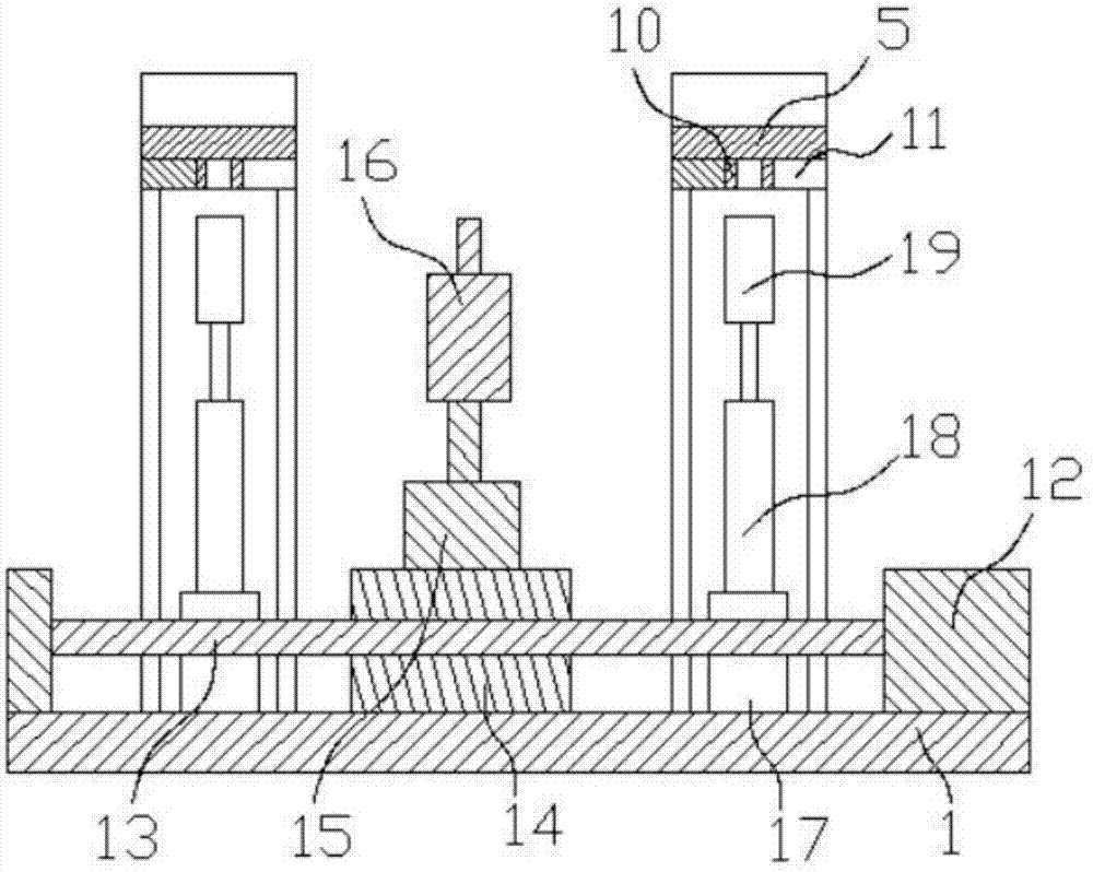
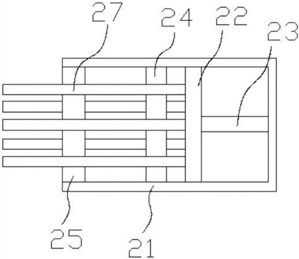
[0032] Such as Figure 1-9 As shown, the specific structure of the present invention is: a double-layer metal pin assembly machine for plugs, which includes a frame 1, and the frame 1 is provided with a conveying mechanism that cooperates with the conveying carrier. The frame 1 is sequentially provided with a pin insertion device 6, a welding device 7 and a blanking device 9 that cooperate with the conveying carrier on the conveying mechanism. It is characterized in that the described pin insertion device 6 includes a The front and rear movable cylinders 41 of the pin insertion, the front and rear mov...


PUM


Abstract

The invention relates to a double-layer metal pin assembly machine for plugs, comprising a frame, a conveying mechanism, a pin device, a welding device and a blanking device. Lifting cylinder and pin pick and place device. The pin pick and place device includes a pick and place body. The center of the lower part of the pick and place body is provided with an arc-shaped groove with an arc of 180 degrees. The lower part of the arc-shaped groove is equipped with an opening and closing device. There is a pressing slot on the main body of the device, the upper part of the pressing slot is provided with a pin pressing cylinder, the lower part of the pin pressing cylinder is connected to a pin pressing block, and the front side of the pick-and-placer is provided with a pin pushing installation block. The lower part of the pin push-in mounting block is provided with a pin push-in lift cylinder, and the pin push-in lift cylinder is connected with the pin push-in lift block. The present invention can not only realize the downward pressing of the pin, but also realize the metal pin The needle insertion operation is realized through the jack, which can meet the two-layer metal needle insertion of the double-layer and half-socket.

Description

technical field [0001] The invention relates to the field of electronic product processing equipment, in particular to a double-layer metal pin assembly machine for plugs. Background technique [0002] With the improvement of science and technology, various electronic products emerge in endlessly. Most of the electronics use plugs. image 3 As mentioned above, it includes a grooved plug body 21, a vertical circuit board 22 is fixed inside the plug body, the circuit board 22 is connected with a circuit wire 23, and a first pin clamp block 24 and a second pin block are arranged in the plug body. The needle card material block 25, the first pin card material block 24 and the second pin card material block 25 are provided with grooves that match the position and cooperate with the metal pins, and the middle part is provided with a jack that cooperates with the metal pins, so During the processing of this type of plug, it is necessary to pass the metal pins 27 through the grooves...

Claims


Application Information

Patent Timeline
Patent Type & Authority Applications(China)
IPC IPC(8): H01R43/20
CPCH01R43/20
Inventor 洪颖邓君
Owner DONGGUAN UNIV OF TECH
Why Eureka
Try Eureka