Operation control method of three-state high-gain current source inverter

A current source type, operation control technology, applied in the direction of converting AC power input to DC power output, electrical components, output power conversion devices, etc., can solve the problems of no public reports of technical solutions, unsuitable driving methods, etc., to achieve Good anti-interference performance, stable operation and improved tracking performance

Active Publication Date: 2019-09-06
HEFEI UNIV OF TECH
View PDF2 Cites 0 Cited by
  • Summary
  • Abstract
  • Description
  • Claims
  • Application Information

AI Technical Summary

Problems solved by technology

Due to the addition of a power switch tube S in the inductance network on the DC side 0 , which is a seven-way switching tube. Therefore, the traditional driving method for the inverter of six-way switching tubes cannot be applied to the inverter of this structure, and there has been no public report on the relevant technical solution so far.

Method used


Image

  • Operation control method of three-state high-gain current source inverter
  • Operation control method of three-state high-gain current source inverter
  • Operation control method of three-state high-gain current source inverter

Examples


Embodiment Construction

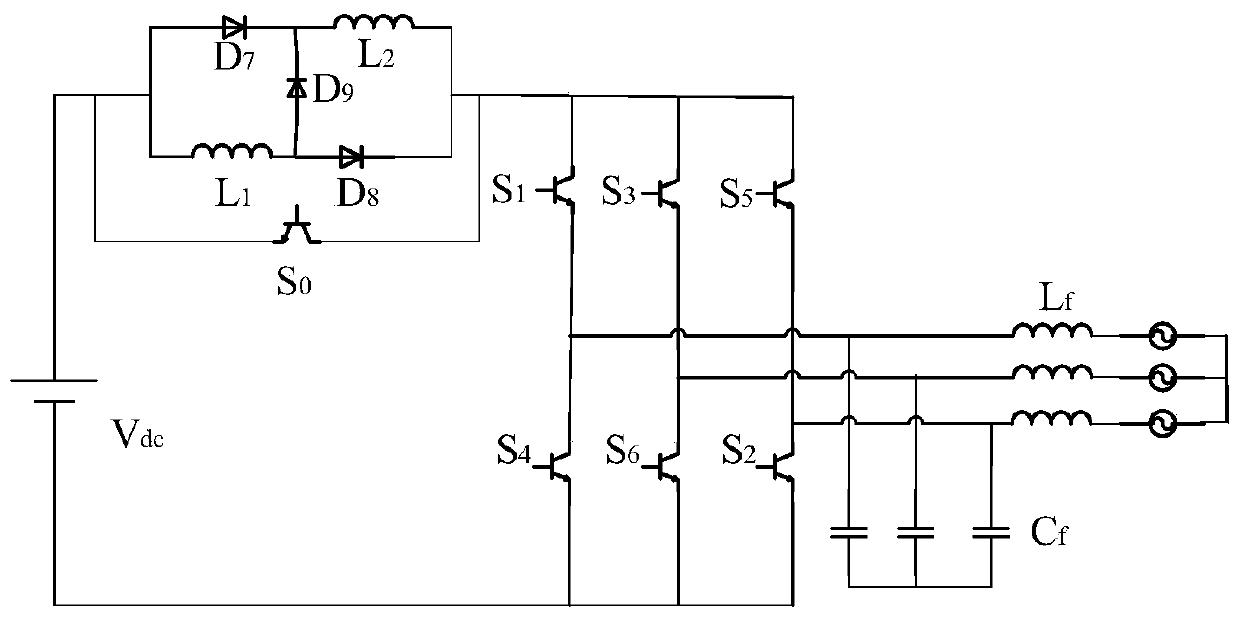
[0047] The principle of the main circuit of the three-state high-gain current source inverter in this embodiment is as follows figure 2 As shown, it includes diode D7, diode D8, diode D9, inductor L1, inductor L2, and power switch S on the DC side of the inverter. 0 The switch inductance network is composed; the power switch tube S 0 It is the seventh switch tube, in addition, there are six switch tubes S 1 -S 6 Forming a conventional three-phase inverter bridge, the inverter has three states, namely the through state, the active state and the freewheeling state.

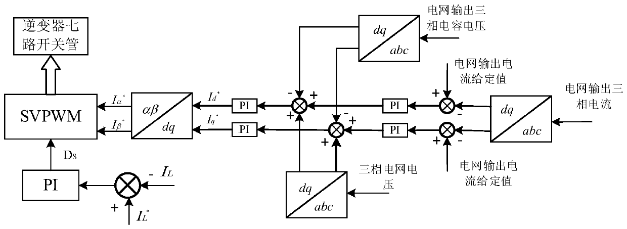
[0048] In this example, for figure 2 The three-state high-gain current source inverter shown, in order to achieve its three-state stable operation, is designed as figure 1 The control block diagram shown, and control according to the following steps:

[0049] Step 1: Perform grid output current control, grid voltage feedforward compensation control, and grid output capacitor voltage control on the AC output side of the in...


PUM


Abstract

The invention discloses a three-state high-gain current source inverter operation control method, which is to control the output current of the power grid, the feed-forward compensation control of the voltage of the power grid, and the output capacitor voltage of the power grid on the AC output side of the inverter. The DC input side of the inverter performs DC current control, and performs space vector pulse width modulation (SVPWM) wave generation according to the obtained control results, thereby driving the seven-way switch tubes of the three-state high-gain current source inverter. Aiming at the high-gain current-type inverter whose publication number is CN103259442A, the present invention provides a suitable three-state high-gain current-source inverter operation control method, which effectively solves the driving problem of its seven-way switch tube and realizes DC stable operation on both the AC side and the AC side.

Description

Technical field [0001] The invention belongs to the field of photovoltaic grid-connected inverters, and more specifically relates to a three-state high-gain current source inverter operation control method. Background technique [0002] In recent years, due to the increasingly severe globalization of energy crisis and environmental issues, solar energy, as a renewable green energy source, is one of the new energy sources that countries are striving to develop. Photovoltaic grid-connected power generation has broad development prospects. In the photovoltaic grid-connected power generation system, the inverter is the core of energy conversion and control. Its performance not only affects and determines whether the entire photovoltaic grid-connected system can operate stably, safely, reliably, and efficiently, but is also the main factor affecting the service life of the entire system. For safety reasons, the output voltage of photovoltaic arrays is generally low and cannot meet t...

Claims


Application Information

Patent Timeline
Patent Type & Authority Patents(China)
IPC IPC(8): H02M7/5387H02M7/5395H02M1/08
CPCH02M1/08H02M7/5387H02M7/5395H02M1/0003
Inventor 茆美琴李延东张榴晨
Owner HEFEI UNIV OF TECH
Why Eureka
Try Eureka