Two-wire two-colour charactron controller

A technology of digital tubes and controllers, applied to instruments, static indicators, etc., can solve the problems of different driving voltages, occupying serial port resources, inconsistent brightness, etc., and achieve the effects of consistent brightness, simplified circuits, and simple and convenient interfaces

Inactive Publication Date: 2004-06-30
中国科学院沈阳科学仪器研制中心
View PDF0 Cites 1 Cited by
  • Summary
  • Abstract
  • Description
  • Claims
  • Application Information

AI Technical Summary

Problems solved by technology

However, the traditional driving method may occupy more CPU I / O ports (in the dynamic scanning mode, 8 seven-segment digital tubes can be driven as an example, 16 CPU I / Os are required, see figure 2 ), or occupy its serial port resources (usually the single-chip microcomputer only has one standard serial port, such as the static driving method of serial->parallel conversion, see image 3 )
[0003] In addition, because the two-color digital tube uses two light-emitting diodes to achieve two-color light-emitting elements, its driving voltage is different, so its brightness is different under the same voltage; Depending on the divided voltage, the current flowing through the common terminal of the digital tube will be different, resulting in inconsistent brightness when displaying different characters

Method used


Image

  • Two-wire two-colour charactron controller
  • Two-wire two-colour charactron controller
  • Two-wire two-colour charactron controller

Examples


Embodiment 1

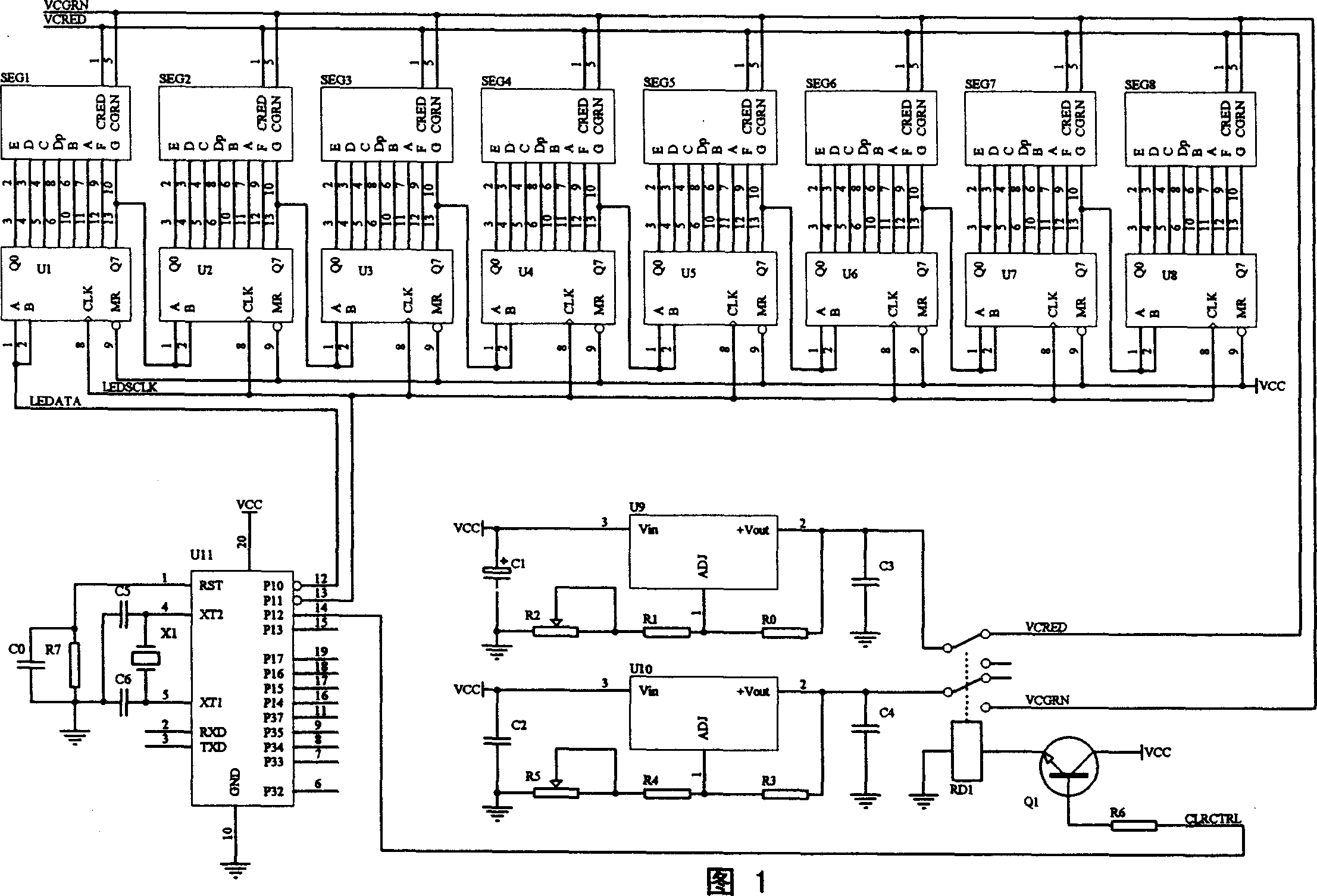
[0016] The present invention consists of the 1st to 8th strings -> parallel conversion logic devices U1 to U8, the 1st to 8th two-color digital tubes SEG1 to SEG8, the 0th to 7th resistors R0 to R7, the 0th to 6th capacitors C0 to C6, the 1st to 8th 2. It is composed of adjustable three-terminal voltage regulator U9~U10, single-chip microcomputer U11, first transistor Q1 and first relay RD1. The specific connection is: first to eighth string -> parallel conversion of pins 1 and 2 of logic devices U1~U8 is Serial data input terminal, pin 13 is the serial data output terminal, the serial data input terminal of the first string -> parallel conversion logic device U1 is the serial data input terminal of the entire drive unit (see the LEDATA network logo in the figure), the signal From pin 12 of the single chip microcomputer U11, its serial data output terminal is cascaded to the serial data input terminal of the next-stage serial->parallel conversion logic device, such as the seria...


PUM


Abstract

The controller comprises 1th-8th series/parallel conversion logic device, 1th-8th two-color digitrons, 1th-2th adjustable regulator with three ends, and single chip. The 1th-8th series/parallel conversion logic device possesses serial data input end and serial data output end. The serial data input end of 1th series/parallel conversion logic device is serial data input of entire driving unit, and signal is from the single chip. The serial data output end is cascaded to serial data input end of next series/parallel conversion logic device. The logic device is connected to stroke ends, decimal ends, and clock in parallel respectively. The 1th-8th two-color digitrons is connected to 1th-2th adjustable regulator with three ends respectively. The invention saves lager amount of I/O wires in dynamic scanning method and synchronous serial ports in static driving method, making digitrons easy to be driven, as well as possessing features of simple to interface and high reliability.

Description

technical field [0001] The invention relates to the field of intelligent instruments, in particular to a two-line and two-color digital tube controller. Background technique [0002] In the field of smart instruments, the display of measurement data is essential. Seven-segment digital tubes are more and more used in various instruments because of their advantages such as high brightness, simple driving and long life. However, the traditional driving method may occupy more CPU I / O ports (in the dynamic scanning mode, 8 seven-segment digital tubes can be driven as an example, 16 CPU I / Os are required, see figure 2 ), or occupy its serial port resources (usually the single-chip microcomputer only has one standard serial port, such as the static driving method of serial->parallel conversion, see image 3 ). [0003] In addition, because the two-color digital tube uses two light-emitting diodes to achieve two-color light-emitting elements, its driving voltage is different, so ...

Claims


Application Information

Patent Timeline
Patent Type & Authority Applications(China)
IPC IPC(8): G09G3/20
Inventor 张利国
Owner 中国科学院沈阳科学仪器研制中心
Why Eureka
Try Eureka