
Medical ultrasonic transducer with wireless transmission function

An ultrasonic transducer, wireless transmission technology, applied in signal transmission systems, ultrasonic/sonic/infrasonic diagnosis, instruments, etc., can solve problems such as difficult handling, inconvenient transducers, heavy cables, etc., to achieve strong practicability and convenience. The effect of flexible use and improved processing speed

Inactive Publication Date: 2018-10-12
芜湖众梦电子科技有限公司
View PDF4 Cites 1 Cited by
  • Summary
  • Abstract
  • Description
  • Claims
  • Application Information

AI Technical Summary

Problems solved by technology

But for a long time, especially for sonographers, the cable connecting the transducer and the ultrasound system has caused great inconvenience to the sonographer in using the transducer, which has always been a major shortcoming of medical ultrasound diagnosis
[0004] (2) Since the cable connecting the transducer to the ultrasound system needs to contain thousands, hundreds or even thousands of coaxial wires from the probe, the probe cable will be quite heavy and difficult to handle
In practice, some sonographers try to solve the problem of the cable by draping the cable over the arm or shoulder during the scan, but in many cases this can lead to repetitive stress injuries to the doctor's arm or shoulder
In addition, despite the sterile protective layer on the outside of the cable, the presence of the cable still increases the risk of infection for the patient when used in surgery
In addition, the display terminals of the traditional ultrasonic diagnostic system connected by cables are all dedicated, with poor portability and often expensive
At the same time, the cable itself for these probes is relatively expensive and is often the most expensive part of the probe

Method used

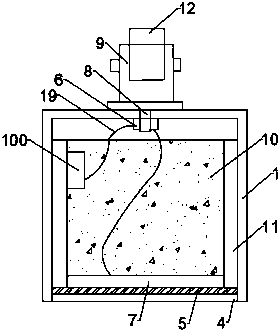
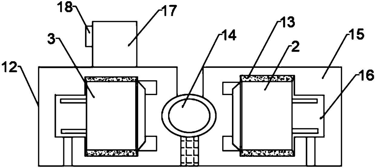
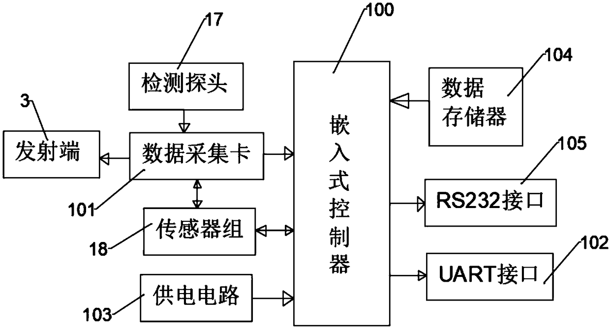

Image

  • Medical ultrasonic transducer with wireless transmission function
  • Medical ultrasonic transducer with wireless transmission function
  • Medical ultrasonic transducer with wireless transmission function

Examples


Embodiment Construction

[0031] The following will clearly and completely describe the technical solutions in the embodiments of the present invention with reference to the accompanying drawings in the embodiments of the present invention. Obviously, the described embodiments are only some, not all, embodiments of the present invention. Based on the embodiments of the present invention, all other embodiments obtained by persons of ordinary skill in the art without making creative efforts belong to the protection scope of the present invention.

[0032] Such as figure 1 As shown, the present invention provides a medical ultrasonic transducer with wireless transmission function, including an insulating shell 1 and an embedded controller 100, the upper surface of the insulating shell 1 is fixedly mounted with a probe connector 9, the The inner wall of the detector connector 9 is inlaid with a detector probe 12, and an inner sleeve 11 is fixedly installed on the inner walls of both sides of the insulating...


PUM


Abstract

The invention discloses a medical ultrasonic transducer with a wireless transmission function. The medical ultrasonic transducer comprises an insulating shell and an embedded controller, wherein the upper surface of the insulating shell is fixedly provided with a detector connector, a detector probe is embedded in the inner wall of the detector connector, the lower end of the detector connector isprovided with an electric conductor, the lower end of the electric conductor penetrates through the inner wall of the insulating shell and is connected with a wire terminal arranged on the inner wallof the insulating shell, both ends of the wire terminal are both provided with connection circuits, and the lower ends of the connection circuits are connected with the embedded controller; a methodof detection of a wireless detector is adopted, cables are replaced by wireless signals, the problems of medical staffs bound by the cables, infection in operation and the like can be solved, and accurate, fast, real-time and high-resolution detection mixed signal data is provided for the data analysis and processing work on a PC or server as soon as possible.

Description

technical field [0001] The invention relates to the technical field of medical ultrasonic transducers, in particular to a medical ultrasonic transducer with a wireless transmission function. Background technique [0002] At present, thanks to the advancement of science and technology, the technology for medical clinical diagnosis is developing rapidly. Among them, the most notable example is the application of nuclear magnetic resonance technology and ultrasound imaging technology in clinical detection and diagnosis. Due to the increasing maturity of ultrasound imaging technology, domestic large and medium-sized hospitals are equipped with ultrasound equipment to carry out black-and-white ultrasound and color ultrasound detection and diagnosis. However, the current medical ultrasonic transducers still have certain defects in signal sending and receiving, processing and control: [0003] (1) At present, the four major medical imaging technologies in modern medical imaging t...

Claims


Application Information

Patent Timeline
Patent Type & Authority Applications(China)
IPC IPC(8): A61B8/00G08C17/02
CPCA61B8/4472G08C17/02
Inventor 张阳
Owner 芜湖众梦电子科技有限公司
Learn More