Mechanical type telescopic water gun based on gear and rack transmission

A rack-and-pinion, mechanical technology, used in hydraulic mining, earth-moving drilling, special mining, etc., can solve the problems of difficult heat dissipation, high sealing requirements, and insufficient clamping force in a sealed environment, so as to improve energy utilization, The effect of improving mining efficiency and free extension angle

Active Publication Date: 2018-04-20
JILIN UNIV
View PDF3 Cites 5 Cited by
  • Summary
  • Abstract
  • Description
  • Claims
  • Application Information

AI Technical Summary

Problems solved by technology

"CN104005767A" discloses an electronically controlled telescopic drilling tool for drilling hydraulic mining, but the remote control technology of the drilling tool is not perfect, the working environment of the stepping motor, reducer, and controller is harsh, and the sealed environment is not easy to dissipate heat. The telescopic part works in the slurry environment, which requires high sealing and is easy to be damaged
"CN203961980U" discloses a telescopic water gun based on spring chuck control, but when the water gun works under the condition of drilling fluid, the clamping force is not enough, the water gun is not fixed reliably, and when the water gun is not extended to the maximum angle, The water gun cannot be retracted, so a new technical solution is urgently needed in the existing technology to solve this problem

Method used


Image

  • Mechanical type telescopic water gun based on gear and rack transmission
  • Mechanical type telescopic water gun based on gear and rack transmission
  • Mechanical type telescopic water gun based on gear and rack transmission

Examples


Embodiment Construction

[0016] In order to illustrate the present invention more clearly, the present invention will be further described below in conjunction with preferred embodiments and accompanying drawings. It should be understood by those skilled in the art. The content specifically described below is illustrative rather than restrictive, and should not limit the protection scope of the present invention.

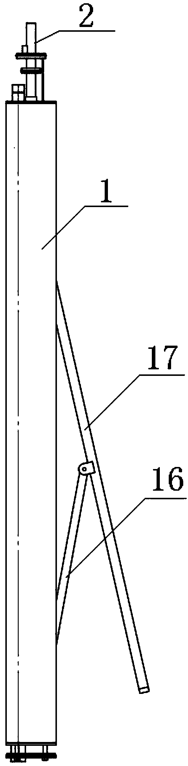
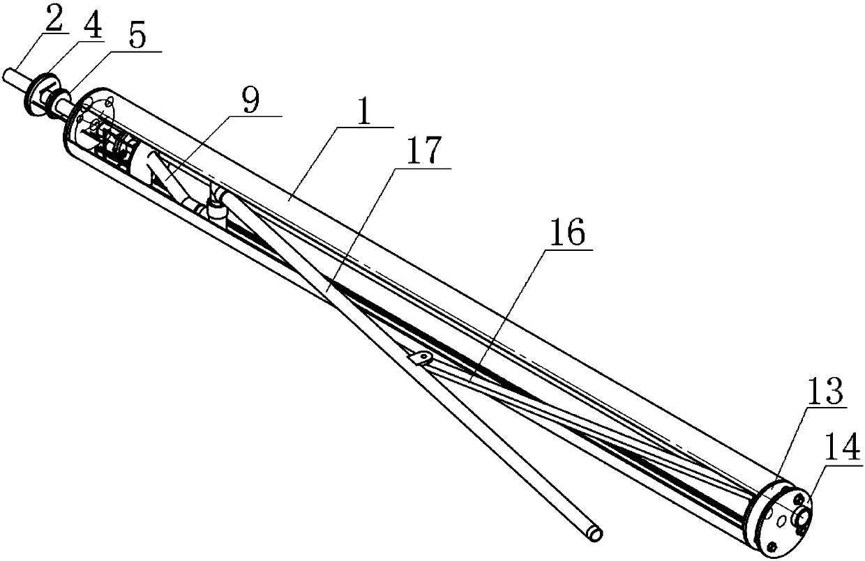
[0017] The present invention proposes a mechanical retractable water gun based on rack and pinion transmission, such as Figure 1 to Figure 6 As shown, the mechanical telescopic water gun is composed of a high-pressure water delivery system, a water gun telescopic system, a water gun brake system and a slag discharge system.

[0018] The high-pressure water delivery system consists of a high-pressure water pipe 2, a high-pressure water pipe rotary joint 5, an eccentric joint 10, a right-angle joint 11, a water gun high-pressure rotary joint 18, and a water gun 17. The high-pressure water p...


PUM


Abstract

The invention discloses a mechanical type telescopic water gun based on gear and rack transmission. The mechanical type telescopic water gun mainly comprises a high pressure water pipe, an upper hydraulic pipe, a hydraulic pipe high-pressure rotary connector, a high-pressure water pipe rotary connector, racks, an eccentric adapter locking bolt, an eccentric adapter, a right-angle connector, an ejection rod, the water gun, a water gun high-pressure rotary connector, a sliding plate, gears, brake plate protective plates, a lower hydraulic pipe, a hydraulic cylinder and a brake plate, wherein ina hydraulic mining process, the high pressure water pipe is lowered according to a required stretching angle of the water gun; when the water gun reaches the set stretching angle, a brake system control valve is turned on to enable the brake plate to brake the gears, so that the stretching angle of the water gun can be fixed, and rocks are crushed. According to the mechanical type telescopic watergun disclosed by the invention, the stretching angle of the water gun is freely adjusted, and the water gun is conveniently stretched and retracted; a distance between a spray nozzle of the water gunand a mining layer is controlled according to the design, and the problem that high pressure water energy is severely weakened because of submerged jetting is solved, so that an aim of increasing anenergy utilization ratio of high-pressure water jetting is fulfilled, and finally, the mining efficiency is improved.

Description

technical field [0001] The invention relates to a telescopic water gun suitable for drilling hydraulic mining, in particular to a mechanical telescopic water gun based on rack and pinion transmission. Background technique [0002] Drilling hydraulic mining technology is to drill a hole in the target area first, then place a high-pressure water gun at the depth of the target mine layer in the drill hole, use the energy carried by the high-speed fluid ejected by high pressure to break the rock, and finally the broken rock and drilling fluid form a solid-liquid mixture , is pumped to the surface by the surface device, and then separates the ore slurry to extract minerals. Borehole hydraulic mining technology has the advantages of low mining cost, high production efficiency, and little impact on the surrounding environment. The high-pressure water nozzle of the traditional hydraulic mining drilling tool is fixed on the outer wall of the drilling tool, and the position of the no...

Claims


Application Information

Patent Timeline
Patent Type & Authority Applications(China)
IPC IPC(8): E21C45/04E21C45/08
CPCE21C45/04E21C45/08
Inventor 陈晨钟秀平孙友宏李刚潘栋彬翟梁皓张颖
Owner JILIN UNIV
Why Eureka
Try Eureka