


Quick Research
Generate reliable direction feasibility study reports for your R&D in just a few steps.

Technical Q&A
Discover and master advanced knowledge NOW. Basics, ideas, possibilities, all at once.

Find Solutions
As an expert in R&D theories, this can generate solutions to your technical problems instantly.

Evaluate Feasibility
Analyze your overall solution with one click, know your potential R&D risks in advance.

Monitor Landscape
Get weekly tech updates, stay abreast of the latest tech innovations and key insights.
Power equipment driven by tides
A technology of power equipment and Inspur, applied in the field of power equipment driven by Inspur, can solve problems such as energy shortage and environmental pollution, and achieve the effects of simple structure, reduced service life and high work efficiency
- Summary
- Abstract
- Description
- Claims
- Application Information
AI Technical Summary
Problems solved by technology
Method used
Image


Examples
Embodiment 1
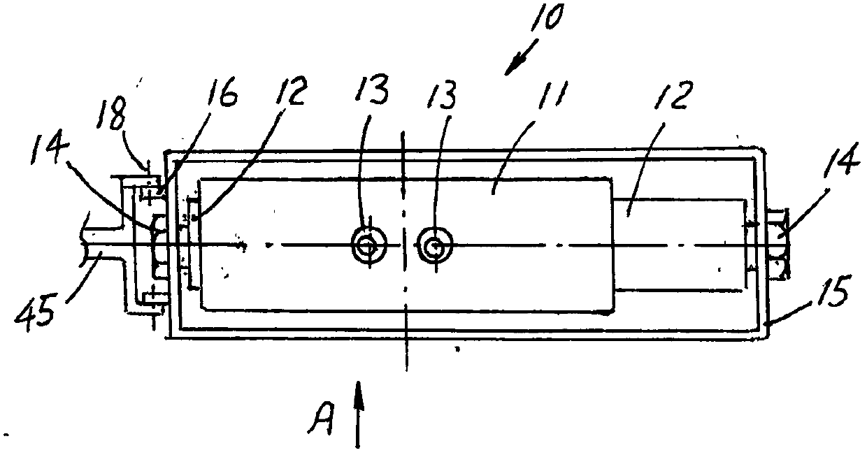
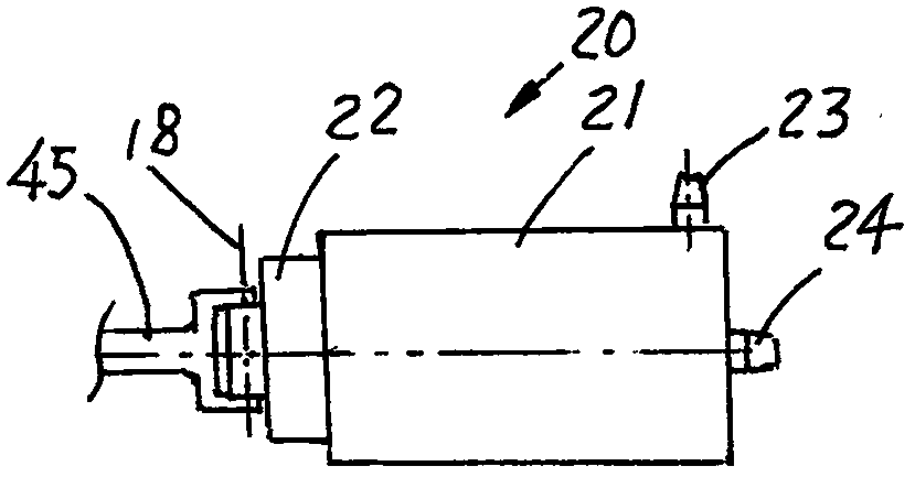
[0030] Embodiment 1. The present embodiment is the power equipment driven by the wave, including a power device and a driving device, both of which are installed on the base, and the power device includes a single-cylinder piston pump 20 or a double-cylinder piston pump 10 and a connecting assembly; as , 1-2, the acting device that present embodiment adopts is double-cylinder piston pump 10, comprises pump case 11, piston 12, dragging frame 15; Two symmetrically arranged pistons are housed on the pump case, and dragging frame 15 is a surrounding pump The frame of shell 11, the ends of two pistons 12 are respectively connected with dragging frame 15 with bolt 14, and at the protrusion 16 place of dragging frame 15 left ends, be connected with connecting shaft 18 in the connection assembly; image 3, the connecting assembly includes an eccentric wheel 47, a connecting rod 45, and a connecting shaft 18. One end of the connecting rod is connected to the drag frame 15 in the work de...
Embodiment 2
[0036] Embodiment 2. Adopt this equipment of another kind of prime mover assembly, as Image 6 , the drive belt 34, the pulley 35, the support wheel 36, and the support wheel shaft 36A in the prime mover assembly in the embodiment 1 are removed, and the hinged rod 34C and the swing rod 35A are replaced, and the swing rod is fixed on the driving gear shaft 37 , the rest of the parts are unchanged as in Embodiment 1; the 2 ends of the hinged rod 34C are hinged with the end of the fork 35A and the tail of the drive arm 32 respectively. The swing of the drive arm 32 driven by the floating ball 31 is transmitted to the driving gear shaft 37 through the hinged rod 34C and the swing rod 35A, so that the driving gear 38 swings thereupon. Connecting rod 45, connecting shaft 18, drive the piston 22 in the single-cylinder piston pump 20 ( Figure 2A ) reciprocating motion to work. The mechanism is simpler, the operation is more reliable, and the maintenance is convenient.
Embodiment 3
[0037] Embodiment 3. Adopt 2 driving devices in parallel to drive a work device to expand the output. Such as Figure 11 , the right side of the figure is a complete set of power equipment with a work device, the base 48 is equipped with a work device 20 including a connecting rod 45, a gear box 49, a floating ball 31, a driving arm 32, a driving belt 34, etc., and the left side of the figure is What is a separate driving device, the driven gear shafts 46 of the two are connected coaxially through a shaft coupling 65, and become a structure in which two driving devices drive a working device 20. The structure is easy to install and disassemble. The driving device on the left side of the figure can be disassembled to do work by using the complete set of equipment. Overrunning clutch is all housed between each driven gear 44 and driven gear shaft 46, as Figure 12 As shown, the overrunning clutch between the driven gear shaft 46 and the driven gear 44 includes an outer ring 44...
PUM
 Abstract
Description
Claims
Application Information
 - R&D Engineer
- R&D Manager
- IP Professional
- Industry Leading Data Capabilities
- Powerful AI technology
- Patent DNA Extraction
Browse by: Latest US Patents, China's latest patents, Technical Efficacy Thesaurus, Application Domain, Technology Topic, Popular Technical Reports.
© 2024 PatSnap. All rights reserved.Legal|Privacy policy|Modern Slavery Act Transparency Statement|Sitemap|About US| Contact US: help@patsnap.com