Multiple feed loop detection method, system and device

A technology of a power supply circuit and a detection method, applied in the field of rail transit, can solve the problems of diode breakdown, no indicator, and inability to quickly find breakdown faults.

Active Publication Date: 2018-04-13
ZHUZHOU ELECTRIC LOCOMOTIVE CO
View PDF16 Cites 6 Cited by
  • Summary
  • Abstract
  • Description
  • Claims
  • Application Information

AI Technical Summary

Problems solved by technology

However, the short-term high voltage or the quality problem of the device itself will cause the diode to be broken down, which will make the circuit between the catenary and the third rail conduct
At this time, if the bow is charged in the warehouse, the current receiver under the car will also be

Method used


Image

  • Multiple feed loop detection method, system and device
  • Multiple feed loop detection method, system and device
  • Multiple feed loop detection method, system and device

Examples


Embodiment Construction

[0040] The following will clearly and completely describe the technical solutions in the embodiments of the present invention with reference to the accompanying drawings in the embodiments of the present invention. Obviously, the described embodiments are only some, not all, embodiments of the present invention. Based on the embodiments of the present invention, all other embodiments obtained by persons of ordinary skill in the art without making creative efforts belong to the protection scope of the present invention.

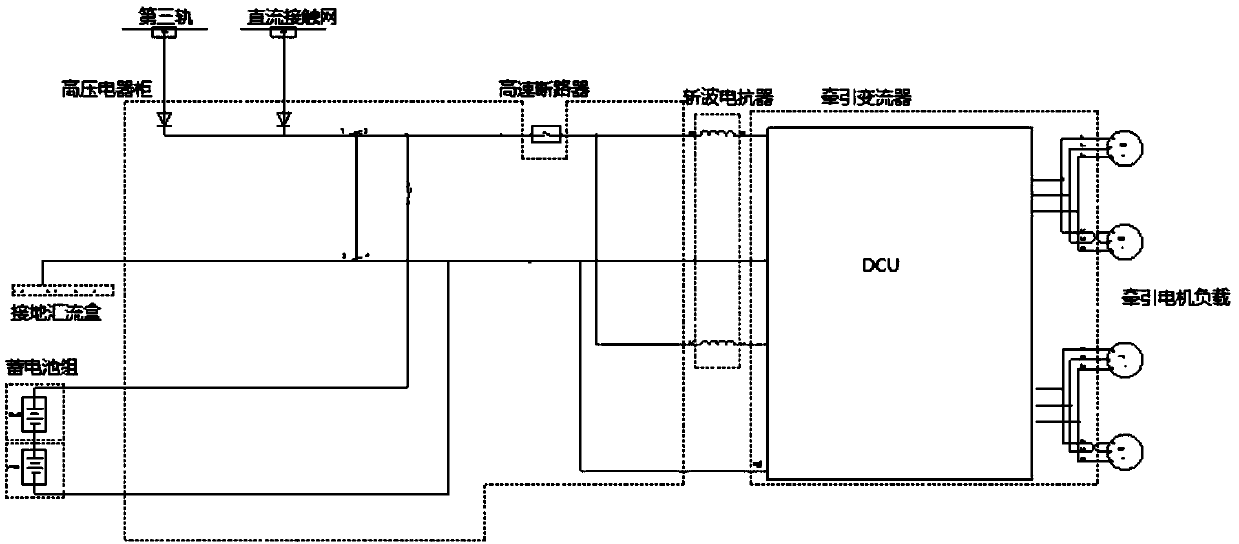
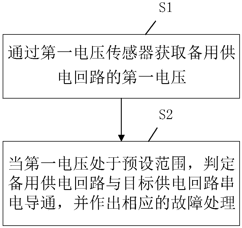
[0041] The embodiment of the present invention discloses a detection method for a multi-power supply circuit, which is applied to the power supply circuit where both the catenary and the third rail are connected to the main transmission system of the locomotive through an isolation conduction device, see figure 2 shown, including:

[0042] Step S1: Obtain the first voltage of the standby power supply circuit through the first voltage sensor;

[0043] Wherein...


PUM


Abstract

The invention discloses a multiple feed loop detection method which is applied to a power supply loop that an overhead line system and a third rail are both connected with a locomotive main driving system through isolative conduction devices. The detection method comprises the steps that first voltage of a stand-by power supply loop is obtained through a first voltage sensor; a current locomotivemain driving system is powered up by a target power supply loop, the target power supply loop is an overhead line system power supply loop or third rail power supply loop, and the stand-by power supply loop is the third rail power supply loop or overhead line system power supply loop in a standby state; when the first voltage is within a preset range, the situation that the stand-by power supply loop and the target power supply loop are powered up in series and conducted is judged, and corresponding failure treatment is made. A multiple feed loop detection system is simple in circuit and smallin occupied space, and can be applied to power supply loops provided with isolative conduction devices. When a series powered-up conductive failure occurs on the stand-by power supply loop, the firstvoltage is changed to be within the preset range, treatment can be timely conducted on the failure after the change is detected, and a protective control measure is taken so as to prevent losses frombeing enlarged.

Description

technical field [0001] The invention relates to the field of rail transit, in particular to a detection method, system and device for a multi-power supply circuit. Background technique [0002] Under the power supply mode of DC catenary, third rail or battery, the traction main circuit of the battery electric engineering vehicle passes the direct current of different voltage levels (such as DC1500V or DC800V) through the high-speed circuit breaker, the filter of the chopper reactor and the traction inverter. After the inverter is turned, the three-phase voltage is provided to the subsequent three-phase AC asynchronous traction motor to meet the operation requirements of the engineering vehicle. The schematic diagram of the main circuit of the battery power engineering vehicle under the three-power supply mode is as follows: figure 1 shown. Among them, the catenary, the third rail and the traction battery are all high-voltage power supplies. In order to avoid series electri...

Claims


Application Information

Patent Timeline
IPC IPC(8): B60M3/00G01R31/02H02J9/02
CPCH02J9/02B60M3/00G01R31/52Y04S20/20Y02B70/30
Inventor 李希宁彭新平郭婉露刘世杰付金张树勋
Owner ZHUZHOU ELECTRIC LOCOMOTIVE CO
Why Eureka
Try Eureka