
Projection equipment and system

A kind of projection equipment and projection technology, applied in the direction of optics, instruments, projection devices, etc., can solve the problem that the projection screen is inconvenient to carry for users, and achieve the effect of being easy to carry and use

Pending Publication Date: 2018-04-06
SHENZHEN WOWOTO TECH CO LTD
View PDF10 Cites 8 Cited by
  • Summary
  • Abstract
  • Description
  • Claims
  • Application Information

AI Technical Summary

Problems solved by technology

[0003] In view of this, the present invention provides a projection device and system, which can improve the existing technology by setting a projection screen, connectors, support components, speakers, image acquisition equipment, controllers, and power storage devices and projection mechanisms to form an integrated machine. The medium projection screen is not easy to carry, which brings troubles to users

Method used


Image

  • Projection equipment and system
  • Projection equipment and system
  • Projection equipment and system

Examples


no. 1 example

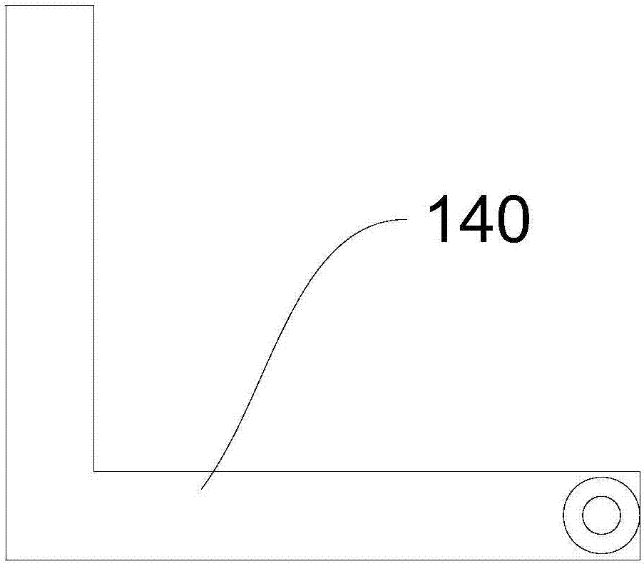
[0031] This embodiment provides a projection device 100, please refer to figure 1 , the projection device 100 includes a projection mechanism 110 , a projection screen 120 , a connector 130 , a support 140 , a speaker 150 , an image acquisition device 160 , a controller 170 and a power storage device 180 . Wherein, one end of the connector 130 is connected to the projection mechanism 110, the other end of the connector 130 is movably connected to one end of the support 140, the other end of the support 140 is connected to the projection screen 120, the speaker 150 is arranged on the projection mechanism 110, and the image acquisition device 160 is arranged The projection mechanism 110 is located at a position close to the light exit channel. The projection mechanism 110 , the speaker 150 , the image capture device 160 are electrically connected to the controller 170 , and the projection mechanism 110 , the speaker 150 , the image capture device 160 and the controller 170 are r...

no. 2 example

[0057] The second embodiment of the present invention provides a projection system, please refer to Figure 9 , the projection system includes a terminal device and the projection device 100 provided in the first embodiment of the present invention. Wherein, the terminal device is coupled with the projection device 100 . The terminal device is used to provide a video source or an image source to the projection device 100 . The terminal device may be electronic equipment such as a host computer, a tablet computer, and a mobile phone.

[0058] To sum up, the projection equipment and system provided by the embodiments of the present invention include a projection screen, a connector, a support, a speaker, an image acquisition device, a controller, and a power storage device in the projection mechanism. Specifically, one end of the connector is connected to the projection mechanism, the other end of the connector is movably connected to one end of the support, the other end of t...


PUM


Abstract

The embodiment of the invention provides projection equipment and a system, and relates to the display equipment field; the projection equipment comprises a projection mechanism, a projection screen,a connector, a support member, a loudspeaker, an image acquisition device, a controller and an electric storage device; one end of the connector is connected with the projection mechanism, and the other end of the connector is movably connected with one end of the support member; the other end of the support member is connected with the projection screen; the loudspeaker is arranged in the projection mechanism; the image acquisition device is arranged in a position, close to the light outlet path, of the projection mechanism. The projection mechanism, the loudspeaker and the image acquisitiondevice are electrically connected with the controller; the projection mechanism, the loudspeaker, the image acquisition device and the controller are respectively electrically connected with the electric storage device. The electric storage device provides power for the projection mechanism, the loudspeaker, the image acquisition device and the controller; the projection mechanism is controlled bythe controller so as to project images to the projection screen; the loudspeaker is controlled by the controller to make sounds, thus integrating the projection screen with the projection mechanism.

Description

technical field [0001] The present invention relates to the field of display devices, in particular, to a projection device and a system. Background technique [0002] Existing projection equipment usually separates the projection part from the projection screen. When performing projection display, it is usually necessary to install a projection screen in the projection area, and then turn on the projection equipment to project onto the projection screen, which is more suitable for schools or work environments. However, when projection display is required outside, the projection screen is usually inconvenient to carry, which brings great troubles to users. Contents of the invention [0003] In view of this, the present invention provides a projection device and system, which can improve the existing technology by setting a projection screen, connectors, support components, speakers, image acquisition equipment, controllers, and power storage devices and projection mechanis...

Claims


Application Information

Patent Timeline
Patent Type & Authority Applications(China)
IPC IPC(8): G03B21/10G03B21/58G03B21/14
CPCG03B21/10G03B21/14G03B21/58
Inventor 张新民
Owner SHENZHEN WOWOTO TECH CO LTD
Learn More