
Work method for protecting hydraulic cylinder against damage

A working method and technology of hydraulic cylinders, applied in the direction of fluid pressure actuation devices, mechanical equipment, etc., can solve problems such as breakage, leakage, mechanical collision, etc., and achieve the effect of avoiding loopholes or damage

Active Publication Date: 2018-04-06
CHONGQING WEIQING HYDRAULIC MACHINERY CO LTD
View PDF6 Cites 0 Cited by
  • Summary
  • Abstract
  • Description
  • Claims
  • Application Information

AI Technical Summary

Problems solved by technology

However, when the hydraulic cylinder bears a large load, since the thrust is proportional to the effective working area, its cylinder diameter is correspondingly large. When the hydraulic cylinder moves to the end of the stroke, it has relatively large kinetic energy. There will be a mechanical collision between the piston and the cylinder head, resulting in impact, noise, and destructive
Under the impact of the piston for a long time, the hydraulic cylinder will be damaged or even leaked, which will affect the stability of the hydraulic system

Method used


Image

  • Work method for protecting hydraulic cylinder against damage

Examples


Embodiment Construction

[0016] The present invention will be described in further detail below by means of specific embodiments:

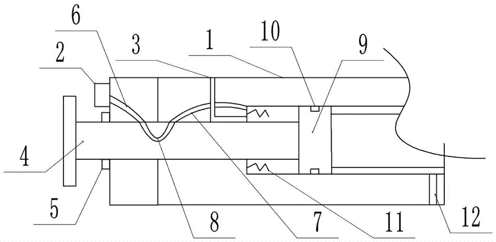
[0017] The reference signs in the drawings of the description include: body 1, high-pressure air pump 2, first oil port 3, piston rod 4, sealing ring 5, first air pipe 6, second air pipe 7, u-shaped pipe 8, piston 9, seal Ring 10, spring 11, second oil port 12.

[0018] The embodiment is basically as figure 1 Shown:

[0019] The anti-damage hydraulic cylinder of the present embodiment comprises a body 1 of the hydraulic cylinder, a piston cavity is opened in the body 1, and a spring 11 for buffering is provided in the piston cavity; a piston 9 is slidably connected to the piston cavity, and both sides of the piston 9 are connected There is a piston rod 4 , a sealing ring 5 is provided at the gap between the body 1 and the piston rod 4 , and a sealing ring 10 is provided at the connection between the piston 9 and the body 1 . The body 1 is provided with a first oil port...


PUM


Abstract

The invention belongs to the field of hydraulic devices and particularly relates to a work method for protecting a hydraulic cylinder against damage. According to the work method, a body of the hydraulic cylinder is involved, a piston cavity is formed in the body, a spring for buffering is arranged in the piston cavity, a piston is connected with the piston cavity in a sliding manner, the two sides of the piston are both connected with piston rods, seal rings are arranged at gaps between the body and the piston rods, and a seal ring is arranged at the connection position between the piston andthe body. The body is provided with a first oil opening and a second oil opening which are used for feeding work oil. The first oil opening is located on the left side of the piston. The second oil opening is located on the right side of the piston. The piston rods are provided with u-shaped pipes. The body is provided with a first gas pipe communicating with the outer side and a second gas pipeextending into the piston cavity. The inlet end of the first gas pipe is connected with an external high-pressure gas pump. When the piston moves to the maximum travel position, the u-shaped pipes enable the firs gas pipe and the second gas pipe to communicate. By the adoption of the work method for protecting the hydraulic cylinder against damage, the impact caused by the piston on the hydrauliccylinder can be reduced, and the hydraulic cylinder is protected against leaks and damage.

Description

technical field [0001] The invention belongs to the field of hydraulic equipment, and in particular relates to a working method of an anti-damage hydraulic cylinder. Background technique [0002] In the machinery industry, the hydraulic cylinder is an important part of power transmission, and the working environment is harsh, especially in the metallurgy, mining and shipping industries, which have high requirements for the operation of machinery and equipment. In the process of mechanical transmission, the hydraulic cylinder In the harsh working environment of high pressure, impact and instability, hydraulic cylinders are widely used in the control process of industrial production. A hydraulic cylinder is a device that converts hydraulic energy into mechanical energy and enables the machine to achieve reciprocating linear motion or swing. Its transmission works smoothly and has high reliability. However, when the hydraulic cylinder bears a large load, since the thrust is pr...

Claims


Application Information

Patent Timeline
Patent Type & Authority Applications(China)
IPC IPC(8): F15B15/14F15B15/22
CPCF15B15/1423F15B15/22F15B15/226F15B2215/30
Inventor 谷山品
Owner CHONGQING WEIQING HYDRAULIC MACHINERY CO LTD
Learn More