
Metal wire distortion machining equipment

A technology of processing equipment and metal wire, which is applied in the field of automatic processing equipment, can solve the problems of low processing efficiency and continuous production, and achieve the effect of improving processing efficiency

Inactive Publication Date: 2018-04-06
ZHEJIANG UNIV OF TECH FENGHUA SMART ECONOMY RES INST
View PDF7 Cites 0 Cited by
  • Summary
  • Abstract
  • Description
  • Claims
  • Application Information

AI Technical Summary

Problems solved by technology

Although processing can be realized by using the above-mentioned manufacturing method, continuous production cannot be realized, resulting in the problem of low processing efficiency

Method used


Image

  • Metal wire distortion machining equipment
  • Metal wire distortion machining equipment
  • Metal wire distortion machining equipment

Examples


Embodiment Construction

[0020] Below in conjunction with the accompanying drawings and embodiments of the description, the specific embodiments of the present invention are described in further detail:

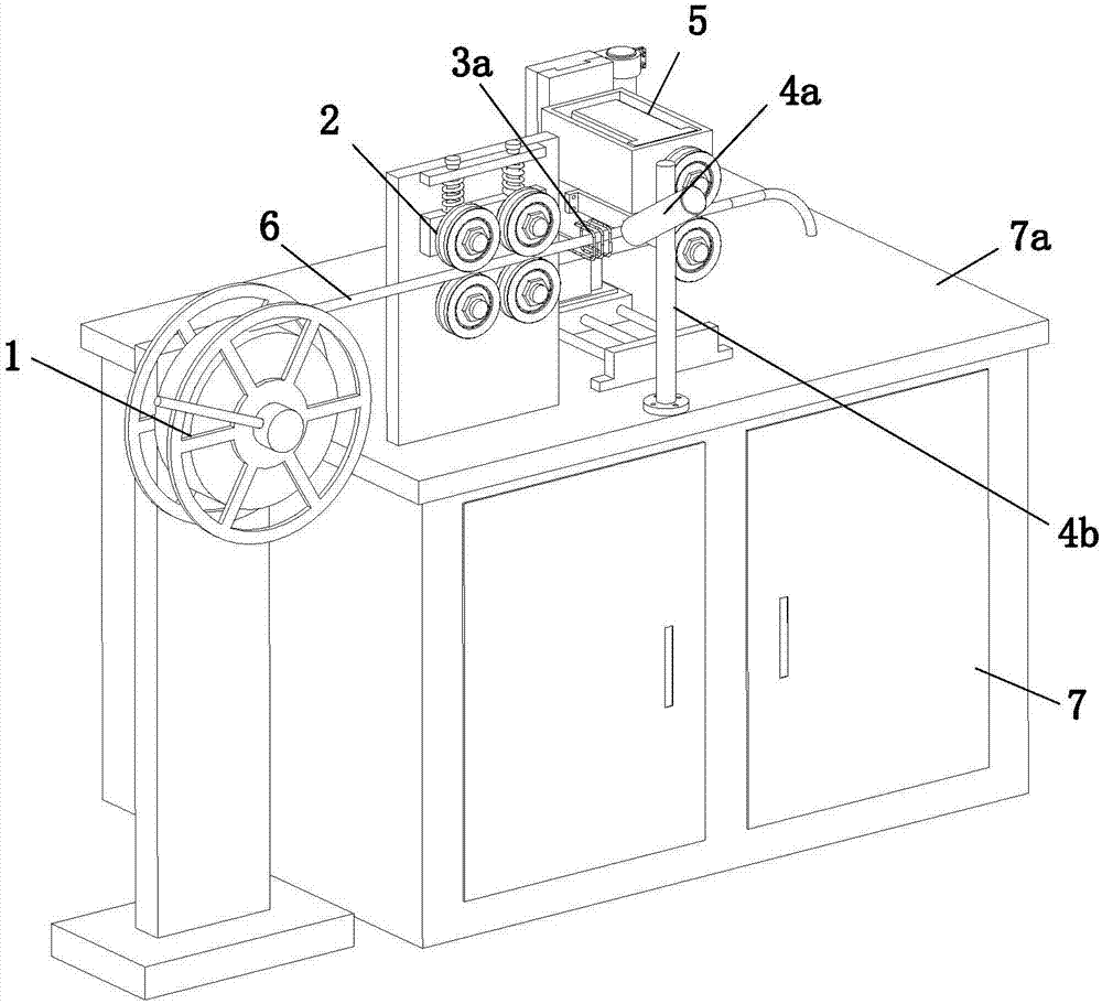
[0021] refer to Figure 1 to Figure 5 The shown equipment for twisting a metal wire includes a wire outlet mechanism 1, a clamping mechanism 2, a heating mechanism, a cooling mechanism and a twisting mechanism 5 arranged in sequence along one direction. 6 is pulled in its own direction, so that the wire 6 passes through the clamping mechanism 2, the heating mechanism and the cooling mechanism in turn. During the movement of the wire 6, the clamping mechanism 2 positions the wire 6, and the heating mechanism controls the outer surface of the wire 6. The circumferential surface is heated, the cooling mechanism cools the outer circumferential surface of the wire rod 6 , and finally the twisting mechanism 5 applies a twisting force to the heating portion of the wire rod 6 .

[0022] Specifically, when t...


PUM


Abstract

The invention relates to the field of automatic machining equipment, in particular to metal wire distortion machining equipment. The metal wire distortion machining equipment comprises a wire outlet mechanism, a clamping mechanism, a heating mechanism, a cooling mechanism and a distortion mechanism which are sequentially arranged in one direction, the distortion mechanism can continuously pull a wire on the wire outlet mechanism in the self direction, the wire sequentially passes through the clamping mechanism, the heating mechanism and the cooling mechanism, the wire is positioned through theclamping mechanism in the wire movement process, the outer circumference face of the wire is heated through the heating mechanism, and the outer circumference face of the wire is cooled through the cooling mechanism; and finally, distortion force is applied to a heating part of the wire through the distortion mechanism. By means of the metal wire distortion machining equipment, continuous distortion machining of the metal wire can be achieved, and the machining efficiency is improved.

Description

technical field [0001] The invention relates to the field of automatic processing equipment, in particular to a twisting processing equipment for metal wires. Background technique [0002] Conventionally, in the bending process of metal wire rods, the front end side of the metal wire rod is clamped on a freely rotatable arm, and the heating part is appropriately moved while heating it with a heating device, and then the metal wire rod is cooled to make the The wire is cooled and shaped. Although processing can be achieved by the above-mentioned manufacturing method, continuous production cannot be achieved, resulting in a problem of low processing efficiency. SUMMARY OF THE INVENTION [0003] The purpose of the present invention is to provide a twisting processing equipment for metal wires in view of the deficiencies of the prior art. [0004] To solve the above problems, the present invention provides the following technical solutions: [0005] A twisting processing eq...

Claims


Application Information

Patent Timeline
IPC IPC(8): B21F7/00
CPCB21F7/00
Inventor 李伟
Owner ZHEJIANG UNIV OF TECH FENGHUA SMART ECONOMY RES INST
Learn More