Corneal contact lens and intraocular illumination system

A contact lens and lighting system technology, applied in ophthalmology treatment, eye testing equipment, medical science, etc., can solve the problems of high risk of eye pollution, extra eye trauma, etc., to achieve less eye infection, improved experience, The effect of ensuring safety

Pending Publication Date: 2018-04-06
杨铭轲
View PDF0 Cites 3 Cited by
  • Summary
  • Abstract
  • Description
  • Claims
  • Application Information

AI Technical Summary

Problems solved by technology

[0004] The main purpose of the present invention is to provide a contact lens, which aims to solve the technical problems that the existing fundus lighting device has additional trauma to the patient's eyes and has a high risk of eye contamination

Method used


Image

  • Corneal contact lens and intraocular illumination system
  • Corneal contact lens and intraocular illumination system
  • Corneal contact lens and intraocular illumination system

Examples


Embodiment Construction

[0023] It should be understood that the specific embodiments described here are only used to explain the present invention, not to limit the present invention.

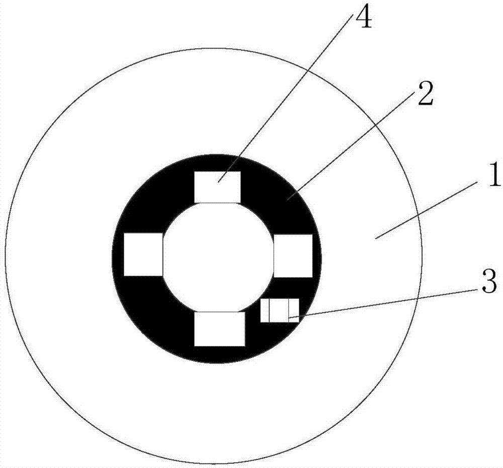
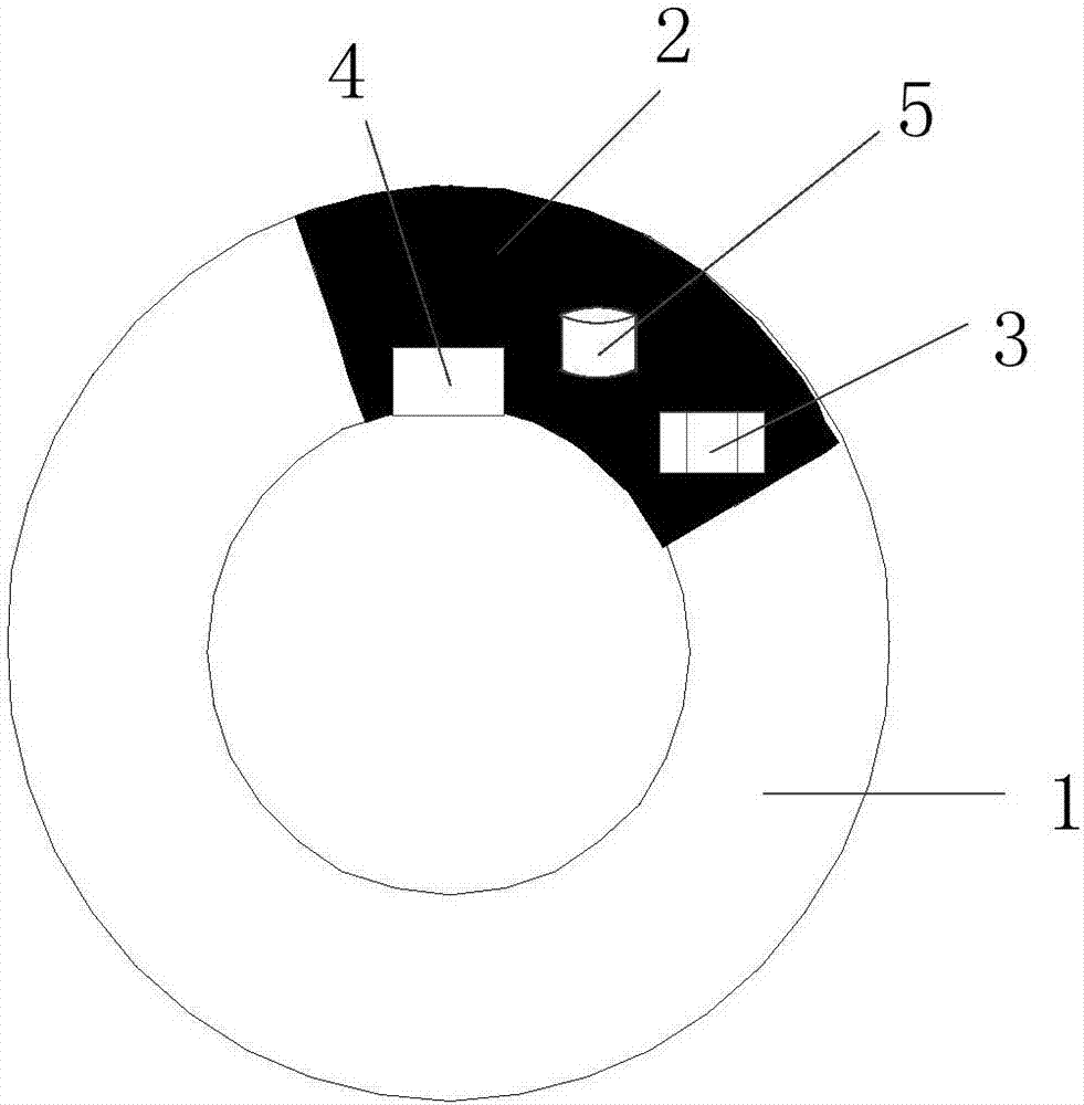
[0024] refer to figure 1 , the embodiment of the present invention proposes a contact lens, including: a contact lens body 1, a flexible circuit board 2, a wireless power receiving circuit 3 and a light emitting element 4; the flexible circuit board 2, the wireless power receiving circuit 3 and the light emitting element 4 is deployed in the designated area of ​​the contact lens body 1; the wireless power receiving circuit 3 and the light emitting element 4 are integrated on the flexible circuit board 2; the wireless power receiving circuit 3 and the light emitting element 4 Electrically connected to supply power to the light-emitting element 4 .

[0025] The contact lens of the embodiment of the present invention realizes the illumination of the patient's fundus by embedding a light-emitting element 4 in the contact...


PUM


Abstract

The invention discloses a corneal contact lens and an intraocular illumination system. The corneal contact lens comprises a corneal contact lens body, a flexible circuit board, a wireless electric energy receiving circuit and a light-emitting element. The flexible circuit board, the wireless electric energy receiving circuit and the light-emitting element are deployed in a designated area in the corneal contact lens body. The wireless electric energy receiving circuit and the light-emitting element are integrated on the flexible circuit board. The wireless electric energy receiving circuit iselectrically connected with the light-emitting element to supply power for the light-emitting element. The corneal contact lens can be directly worn on the eyes of a patient, and the light emitted bythe light-emitting element after electrification directly penetrates into pupils to be diffused to the parts needing lighting of eye grounds. The soft corneal contact lens body completely wraps the light-emitting element, the biocompatibility and wearable property of the corneal contact lens are verified, the corneal contact lens does not bring any additional eye hurt to the patient while the demand of lighting the eye grounds of the patient is met, and is safe and practical.

Description

technical field [0001] This invention relates to medical devices, and more particularly to contact lenses and intraocular lighting systems. Background technique [0002] During various eye examinations and eye surgeries, it is necessary to illuminate the back of the patient's eye. Usually, a puncture is used to make a hole and the light source is introduced into the eye. Usually, the sclera is cut and a tiny fundus light is placed into the eye through the incision. In the vitreous, but this method will cause more trauma to the patient's eyes. Moreover, most of the existing fundus lighting lamps are a single optical fiber filament, one end of which is connected with a high-intensity light source through a connector, and the other end is introduced into the vitreous body of the eye through a supporting component. After power is applied, the light is transmitted through the optical fiber and projected through the vitreous body To the fundus that needs to be illuminated, but th...

Claims


Application Information

Patent Timeline
IPC IPC(8): A61F9/00A61B3/00
CPCA61B3/0008A61F9/0017
Inventor 杨铭轲
Owner 杨铭轲
Why Eureka
Try Eureka