
Light source capable of adjusting color temperatures and color rendering indexes

An adjustable color temperature technology, applied in the direction of light source, light source fixing, lighting and heating equipment, etc., can solve the problems of increasing LED gold wire breakage and open circuit, inconsistent power density in different areas, thermal imbalance and other problems, so as to achieve unsatisfactory reliability of the whole lamp. Damaged, no risk of thermal mismatch, long life effects

Pending Publication Date: 2018-03-30
APT ELECTRONICS
View PDF3 Cites 5 Cited by
  • Summary
  • Abstract
  • Description
  • Claims
  • Application Information

AI Technical Summary

Problems solved by technology

This invention conforms to the technical characteristics of coating phosphors with different color temperatures in different areas. The obvious disadvantage of this invention is that the obtained color temperature can only be between the color temperature of the cool white light source area and the color temperature of the warm white light source area on the chromaticity diagram. Belong to limited color temperature adjustable
Another fatal shortcoming of this invention is that in the process of adjusting the color temperature, due to the control of the power output in different areas, thermal imbalance and serious thermal mismatch of the fluorescent conversion material will greatly increase the probability of the LED gold wire breaking and opening.
This invention has a great disadvantage: this technology can only adjust the color temperature within a relatively narrow range, and the locus composed of the set of all available color temperatures is oblique to the black body radiation line, at the upper right and lower left two The direction is far away from the black body radiation, which further limits its practical significance
[0007] As another example, the Chinese patent with the patent notification number CN105261613A discloses a technical solution to use LED chips of different colors to form independently controlled branches to adjust the color temperature of the light source. The significant disadvantage of this technology is that the spectrum is discontinuous, and In the process of regulation, the power density in different areas is inconsistent, which can easily lead to disconnection and open circuit of the gold wire due to thermal imbalance

Method used


Image

  • Light source capable of adjusting color temperatures and color rendering indexes
  • Light source capable of adjusting color temperatures and color rendering indexes
  • Light source capable of adjusting color temperatures and color rendering indexes

Examples


Embodiment 1

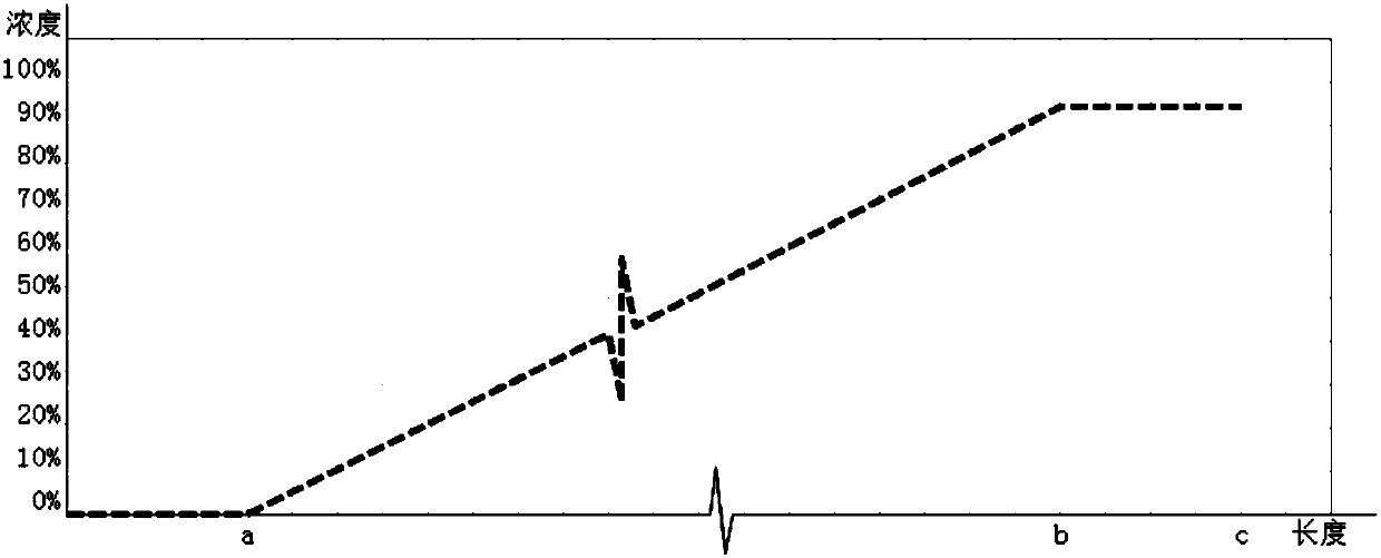
[0035] The invention discloses a light source with adjustable color temperature and display index, such as Figure 1-4 As shown, it includes a substrate 1, a blue light emitting diode 2, a variety of fluorescent diaphragms 4, and a plurality of control modules 5; the blue light emitting diode 2 is electrically connected to the substrate 1, and the fluorescent diaphragm 4 is installed on the light output path of the blue light emitting diode 2 21, each fluorescent membrane 4 is connected to a control module 5 correspondingly.

[0036]Specifically, the connection between the blue light emitting diode 2 chip and the substrate 1 can be through front-chip gold wire bonding or flip-chip eutectic welding.

[0037] In this embodiment, the control module 5 includes a control core and an action actuator; the control core receives an externally input color temperature control signal, and calculates and outputs a pulse waveform for adjusting the position of the fluorescent diaphragm 4 thr...

Embodiment 2

[0049] The present invention provides yet another light source with adjustable color temperature and color display, such as Figure 5 , 6 As shown, the structure of this embodiment is basically the same as that of Embodiment 1, and the difference is that the red fluorescent diaphragm 43, the green fluorescent diaphragm 44, and the yellow fluorescent diaphragm 45 of this embodiment are all circular, and they pass through the rotating shaft Placed concentrically; the distribution of red fluorescent conversion material 421, green fluorescent conversion material 422, and yellow fluorescent conversion material 423 on the corresponding circular red fluorescent membrane 43, green fluorescent membrane 44, and yellow fluorescent membrane 45 is: along the circular In the circumferential direction of the circle, the concentration is distributed from high to low, along the radial direction of the circle, the concentration is equal, and the highest concentration and the lowest concentratio...


PUM


Abstract

The invention discloses a light source capable of adjusting color temperatures and color rendering indexes. The light source comprises a substrate, a blue light emitting diode, multiple fluorescent membranes and control modules correspondingly connected with the fluorescent membranes, wherein the blue light emitting diode is installed on the substrate, and the fluorescent membranes are installed on a light emitting light path of the blue light emitting diode according to a particular order. According to the light source, externally-output color temperature control signals are received throughcontrol cores, fluorescent membrane adjusting signals are calculated and output through preset control programs, action executing mechanisms receive the signals of the control cores to drive the fluorescent membranes to act and enable the overlap positions of the fluorescent membranes to change, and therefore blue light excites fluorescent conversion materials with different proportions, that is to say, the different color temperatures and color rendering indexes can be obtained. According to the light source, large-range continuous adjustment of the color temperatures and the color renderingindexes is achieved, LED driving portions only need to conduct constant outputting, and the light source has no thermal mismatch risks and is safe, reliable, low in cost and long in service life.

Description

technical field [0001] The invention belongs to the technical field of LEDs, and in particular relates to a light source with adjustable color temperature and display. Background technique [0002] In the field of LED lighting packaging, the CIE1931 2° visual space chromaticity diagram is commonly used. Conventional lighting usually divides different white light color regions along the black body radiation line, such as ANSI 7th-order square patch or 3rd-order and 5th-order MacAdam ellipse, etc. Special lighting usually defines a special area on both sides of the black body radiation line / below as the white light color area. The same color area is considered to be similar in color and can be replaced equally. However, due to the large color coordinate span between different color areas, it is considered to be White light of different colors. For a given ordinary white lighting source, its color coordinates only belong to a certain color zone, and cannot be compatible with d...

Claims


Application Information

Patent Timeline
IPC IPC(8): F21K9/20F21K9/64F21V19/00F21Y115/10
CPCF21K9/20F21K9/64F21V19/002F21V23/004F21Y2115/10
Inventor 曾照明刘桂良陈智波姜志荣
Owner APT ELECTRONICS
Learn More