
Automatic iron core welding equipment

A welding equipment and iron core technology, applied in the field of iron core welding, can solve the problems of far-reaching overall mechanization, low work efficiency, manual operation, etc., and achieve the effect of reducing manpower burden, high pass rate, and improving work efficiency

Pending Publication Date: 2018-03-30
JIAXING SHIMIZU ELECTRONICS
View PDF2 Cites 0 Cited by
  • Summary
  • Abstract
  • Description
  • Claims
  • Application Information

AI Technical Summary

Problems solved by technology

Both of these two patents have improved the welding efficiency of the iron core to a certain extent, and realized mechanization in the steps of welding torch or pressing. However, they are still far from the overall mechanization, and the various loading and feeding processes require manual operation. The work efficiency is low, the single shaping, conveying and welding process is too slow and the effect is not obvious, it is difficult to meet the needs of the existing industry

Method used


Image

  • Automatic iron core welding equipment
  • Automatic iron core welding equipment
  • Automatic iron core welding equipment

Examples


Embodiment Construction

[0029] Attached below Figure 1~8 The technical scheme in the embodiment of the present invention is described:

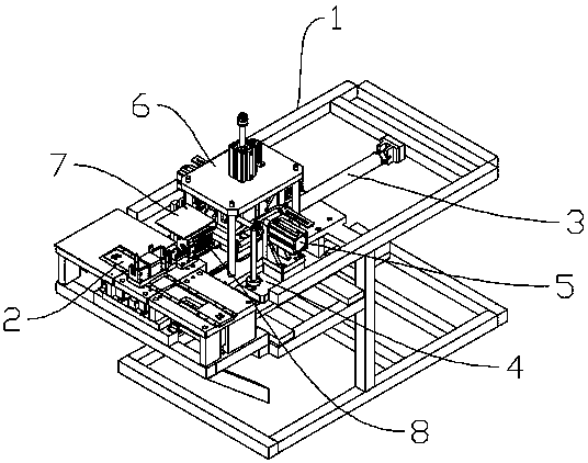
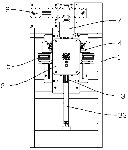
[0030] Such as figure 1 As shown, the present invention provides an automatic iron core welding equipment, including a workbench 1, a clamping mechanism 2, a feeding mechanism 3 and a welding mechanism 4, and the clamping mechanism 2, the feeding mechanism 3 and the welding mechanism 4 are all arranged on the working On the platform 1, the clamping mechanism 2 is arranged on the feeding mechanism 3, and the welding mechanism 4 cooperates with the clamping mechanism 2.

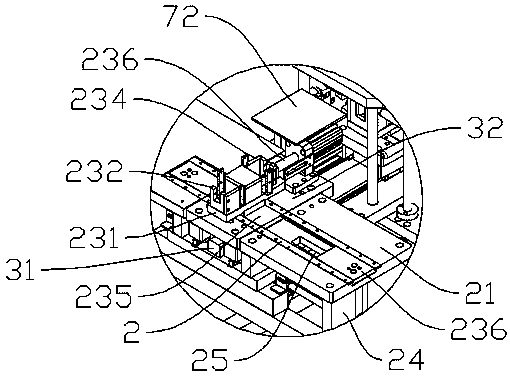
[0031] Such as Figure 1~8 In order to improve the safety performance during welding, a protective cover 7 is provided on the workbench 1, and the heat generated by welding, waste gas or welding slag is isolated from the direct contact with the human body by using the protective cover 7 to ensure welding safety. The side is provided with an opening 71 for the feeding table 32 to pass through. The...


PUM


Abstract

The invention discloses automatic iron core welding equipment. The automatic iron core welding equipment comprises a workbench, a clamping mechanism, a feeding mechanism and welding mechanisms. The welding mechanisms are matched with the clamping mechanism, and the clamping mechanism comprises a clamping table, a clamping rail and at least two clamping stations. The clamping stations are used foriron core placement, the clamping rail is arranged on the clamping table, and the clamping stations are arranged on the clamping rail and capable of moving on the clamping rail. The feeding mechanismcomprises a feeding rail, a feeding driving mechanism and a feeding table. The feeding driving mechanism drives the feeding table to move in the feeding rail, the feeding rail and the clamping rail are intersected perpendicularly, and the clamping stations are capable of moving in the clamping rail to the feeding rail to be clamped in the feeding table. The welding mechanisms are arranged on two sides of the feeding rail, and each welding mechanism comprises a motor slide table, a motor and a welding gun. The automatic iron core welding equipment is high in automation degree, double-station welding is realized, and welding efficiency is greatly improved.

Description

technical field [0001] The invention relates to the technical field of iron core welding, in particular to an automatic iron core welding equipment. Background technique [0002] As one of the indispensable basic equipment in the power system, the reactor has been greatly developed in recent years driven by technological progress. Reactors are also called inductors. When a conductor is energized, it will occupy a certain space. Scope produces a magnetic field, so all electrical conductors capable of carrying current are inductive in a general sense. However, the inductance of the energized long straight conductor is small, and the magnetic field generated is not strong, so the actual reactor is in the form of a solenoid wound with wires, which is called an air-core reactor; sometimes in order to make the solenoid have a larger inductance, The iron core is inserted into the solenoid, which is called iron core reactor. Reactance is divided into inductive reactance and capaci...

Claims


Application Information

Patent Timeline
Patent Type & Authority Applications(China)
IPC IPC(8): B23K37/00B23K37/04B23K37/02
CPCB23K37/00B23K37/0211B23K37/0435
Inventor 不公告发明人
Owner JIAXING SHIMIZU ELECTRONICS
Learn More