
U type silicon carbon rod

A silicon carbide rod, U-shaped technology, applied in the direction of heating element, heating element shape, ohmic resistance heating parts, etc., can solve the problems of silicon carbide rod material brittleness, uneven vibration fracture, etc., to improve the connection stability and improve the overall The effect of strength and structural stability

Inactive Publication Date: 2018-03-27
河南格锐新材料科技有限公司
View PDF0 Cites 1 Cited by
  • Summary
  • Abstract
  • Description
  • Claims
  • Application Information

AI Technical Summary

Problems solved by technology

[0003] The existing silicon carbide rod material is very brittle, and it is easy to be irreparably broken due to uneven vibration during handling, placement, installation, etc. This kind of fracture is especially serious for U-shaped silicon carbide rods.

Method used


Image

  • U type silicon carbon rod
  • U type silicon carbon rod

Examples


Embodiment Construction

[0014] The present invention will be further described below in conjunction with the accompanying drawings and specific preferred embodiments, but the protection scope of the present invention is not limited thereby.

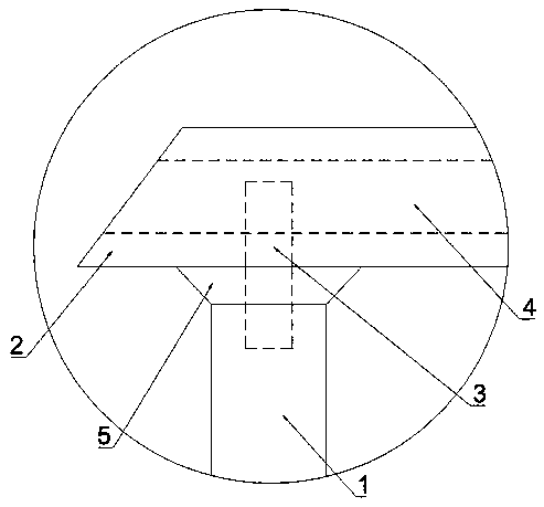
[0015] see Figure 1-2 The U-shaped silicon carbide rod shown includes a vertically connected heating part 1 and a connecting part 2. There are two heating parts 1, one end is an electrode, and the other end is connected to both ends of the connecting part 2 by tenon joints. The connection end is provided with a square connector 3, and a connection plate 4 is built in the connection part 2, and a slot corresponding to the square connector 3 is provided at the corresponding position, and the connection between the heating part 1 and the connection part 2 is welded by external welding Out of the annular reinforcing ring 5, both ends of the connecting portion 2 are also provided with chamfers.

[0016] In the present invention, the mortise joint structure of the h...


PUM


Abstract

U-shaped silicon carbide rods provide a non-metallic high-temperature heating element, including a heating part and a connecting part. The end is provided with a square connection head, and a connection plate is built in the connection part, and a slot corresponding to the square connection head is opened at the corresponding position. Both ends of are also set to chamfer. The invention has reasonable design, convenient use and stable structure.

Description

technical field [0001] The invention belongs to the field of high-temperature components, in particular to a U-shaped silicon carbide rod. Background technique [0002] Silicon carbide rod is made of high-purity green hexagonal silicon carbide as the main raw material, processed with some ingredients, and then sintered at a high temperature of 2200 ° C. It is a non-metallic high-temperature electric heating element with various shapes such as rods and tubes. . Silicon carbide rods have high service temperature, high temperature resistance, oxidation resistance, corrosion resistance, fast temperature rise, and long life. Strong, can also be matched with automatic electronic control equipment, can obtain accurate constant temperature, and can automatically adjust the temperature according to the curve according to the needs of the production process. It is easy to use, safe and reliable. It has been widely used in high-temperature fields such as electronics, magnetic materia...

Claims


Application Information

Patent Timeline
Patent Type & Authority Applications(China)
IPC IPC(8): H05B3/42H05B3/08
CPCH05B3/42H05B3/08
Inventor 胡耀伟
Owner 河南格锐新材料科技有限公司
Learn More