
Switch capacitive converting circuit, and charging control system and method

A technology of switched capacitors and conversion circuits, applied in the field of power supply, can solve the problems of increased heat dissipation temperature of switched capacitor converters, increased losses of switched capacitor converters, and decreased conversion efficiency, so as to reduce system complexity, increase power consumption, reduce The effect of loss

Active Publication Date: 2018-03-23
HUAWEI DIGITAL POWER TECH CO LTD
View PDF3 Cites 13 Cited by
  • Summary
  • Abstract
  • Description
  • Claims
  • Application Information

AI Technical Summary

Problems solved by technology

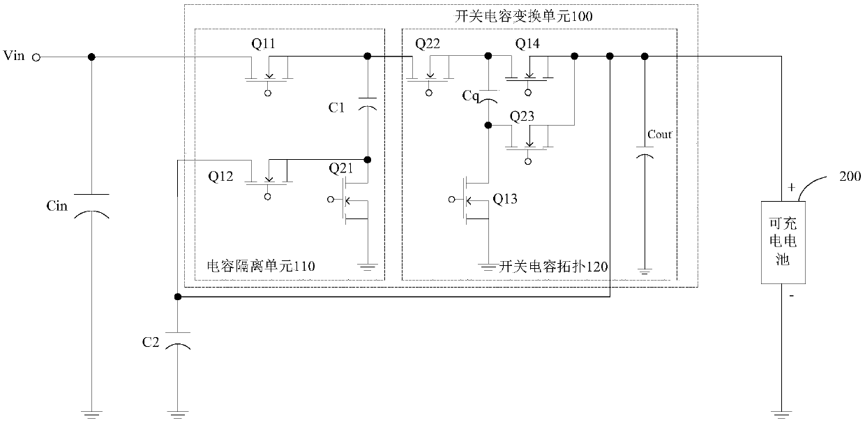
like figure 1 As shown, the typical 2:1 switched capacitor conversion topology composed of Q12, Q22, Q13, Q23, C1 and Co; compared with the 2:1 switched capacitor conversion topology, the 3:1 switched capacitor conversion topology increases Two switching tubes in series, the power input from the input Vin produces losses on these two switching tubes, compared with the 2:1 type switched capacitor conversion topology, the conversion efficiency decreases
That is, the power serial transmission of the traditional 3:1 switched capacitor converter leads to an increase in the loss of the switched capacitor converter, which in turn leads to an increase in the heat dissipation temperature of the switched capacitor converter, and finally leads to an increase in the heat dissipation temperature of the mobile terminal.

Method used


Image

  • Switch capacitive converting circuit, and charging control system and method
  • Switch capacitive converting circuit, and charging control system and method
  • Switch capacitive converting circuit, and charging control system and method

Examples


Embodiment Construction

[0037] In order to increase the charging power, the traditional charging integrated circuit (Buck conversion circuit) needs to increase the volume of the inductor and the area of ​​the charging integrated circuit. However, the size of the mobile terminal is limited and cannot provide a large space for the charging integrated circuit. Therefore, the traditional charging Integrated circuits don't work. It is preferred to use a 2:1 switched capacitor converter. However, as the charging current increases to more than 8A, the input current exceeds the maximum input current of 5A in the 2:1 switched capacitor converter circuit. Therefore, it is necessary to further increase the voltage conversion ratio of the switched capacitor converter. However, the transmission power of the switched capacitor converter with relatively high voltage conversion is transmitted in series, and the loss increases, resulting in a decrease in conversion efficiency. At the same time, the heat dissipation t...


PUM


Abstract

The invention provides a switch capacitive converting circuit, and a charging control system and method. In the switch capacitive converting circuit, the input ends of N levels of switch capacitive conversion units are connected in series successively and the output ends of the same are connected in parallel to obtain a first power supply branch which supplies power to a load; a first capacitor serves as a second power supply branch to supply power to the load; and power in the first power supply branch and power in the second power supply branch are transmitted in parallel. Compared with a manner that the power is transmitted in series, a power transmission path passes fewer devices in the parallel power transmission manner; and thus, power loss in the transmission path can be reduced, and the transmission efficiency in the switch converting circuit is improved.

Description

technical field [0001] The invention belongs to the technical field of power supplies, and in particular relates to a switched capacitor conversion circuit, a charging control system and a method. Background technique [0002] In the field of mobile terminals, due to the limited volume of the mobile terminal, the capacity of the battery in the mobile terminal cannot be too large, therefore, the short battery life of the mobile terminal has become a problem to be solved in this field. At present, fast charging has become a main way to solve the short battery life. As the name implies, fast charging is to increase the charging speed. There are two directions to increase the charging speed. One is to increase the charging voltage, and the other is to increase the charging current. However, increasing the charging voltage will increase the heat generated during the charging process, accelerate battery aging and may cause There are potential safety hazards, and the actual effect...

Claims


Application Information

Patent Timeline
Patent Type & Authority Applications(China)
IPC IPC(8): H02M3/07H02J7/00
CPCH02M3/07H02J2207/20H02J7/00H02M3/071H02J7/0068H02J7/00712Y02B70/10H02M1/0074H02M1/0058H02M1/007H02M3/137H02M3/1584
Inventor 侯庆慧阳成
Owner HUAWEI DIGITAL POWER TECH CO LTD
Learn More