Novel bolt-ball joint and preparation method thereof

A technology of bolt balls and joints, which is applied to casting molding equipment, casting molds, cores, etc., can solve the problems of single large bolt ball joints and affect the safety and stability of structures, and achieve improved safety and stability, dimensional stability, and force transmission. The effect of a clear route

Pending Publication Date: 2018-03-23
HENAN UNIVERSITY
View PDF4 Cites 4 Cited by
  • Summary
  • Abstract
  • Description
  • Claims
  • Application Information

AI Technical Summary

Problems solved by technology

[0005] The present invention aims at the problem that the single weight of the bolt ball joint is relatively large in the prior art, which affects the safety and stability of the structure, and provides a new type of large-diameter bolt ball joint and its preparation method based on topology optimization, which optimizes the bolt ball with a diameter greater than 300mm According to the analysis, the self-weight of the bolt ball joint can be greatly reduced on the basis of satisfying the bearing performance of the bolt ball joint, and the use performance and safety performance of the bolt ball joint are improved.

Method used


Image

  • Novel bolt-ball joint and preparation method thereof
  • Novel bolt-ball joint and preparation method thereof
  • Novel bolt-ball joint and preparation method thereof

Examples


Embodiment Construction

[0032] In order to make the technical purpose, technical solution and beneficial effect of the present invention clearer, the technical solution of the present invention will be further described below in conjunction with the drawings and specific embodiments.

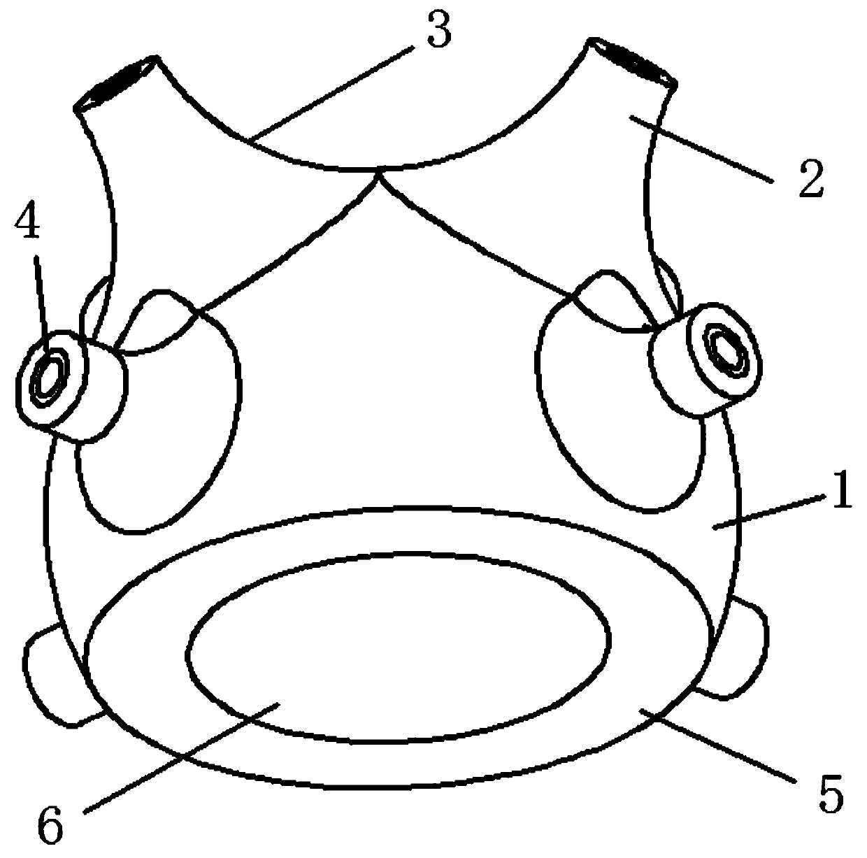
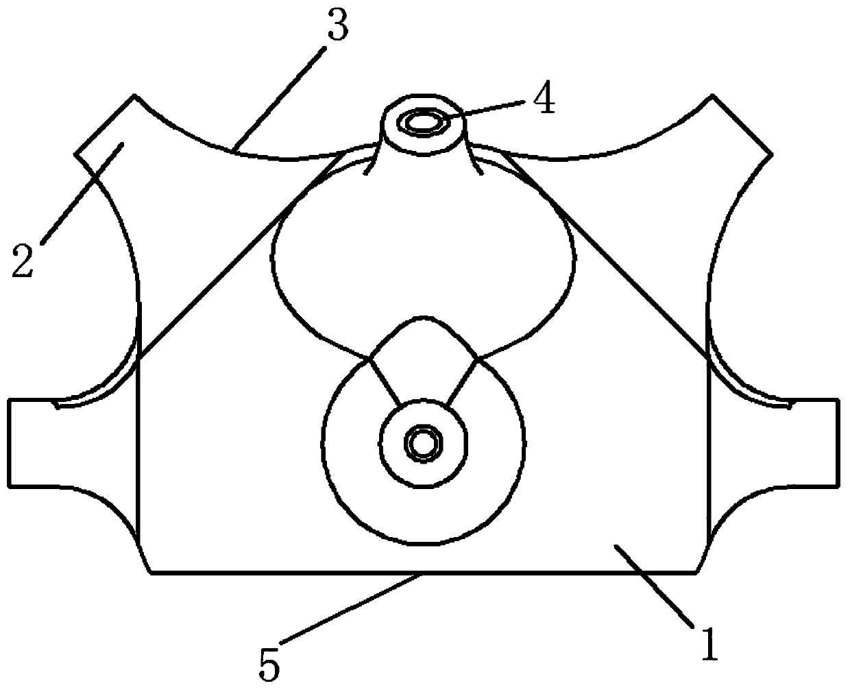
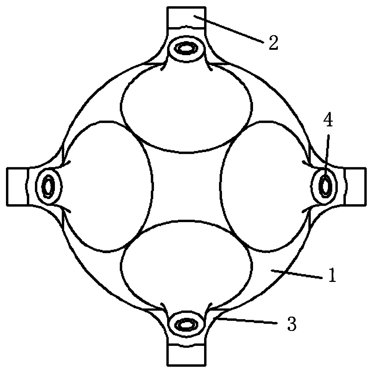
[0033] Such as Figure 1 to Figure 5 As shown, the new bolted ball joint of the present invention includes a steel ball 1 with a cavity structure inside and a branch pipe 2 arranged on the steel ball 1 for connecting and carrying steel rods. The steel ball 1 and the branch pipe 2 Integral molding, the steel ball 1 is a partially cut spherical crown, and the height of the spherical crown is greater than the radius of the steel ball, that is, the cut part of the steel ball 1 is less than half the size of the steel ball 1, and the cut surface of the steel ball is used as the The bottom surface 5 of the steel ball, the bottom surface 5 of the steel ball 1 is a plane circular structure, and the interior of the steel ball 1 ...


PUM


Abstract

The invention relates to a novel bolt-ball joint and a preparation method thereof, and belongs to the technical field of bolt-ball joint design. The novel bolt-ball joint comprises a steel ball and branch tubes, a cavity structure is arranged inside the steel ball, the branch tubes are arranged on the steel ball and used for connecting and bearing steel rods, the steel ball and the branch tubes are integrally formed, the steel ball is in the shape of a partially cut ball crown, the height of the ball crown is larger than the radius of the steel ball, the branch tubes with solid structures arearranged outwards along the normal direction of the steel ball and uniformly distributed along the circumferential direction of the steel ball, counter bored holes are formed in the branch tubes alongthe normal direction, fillet surfaces for smooth coherent transition of the adjacent branch tubes are arranged on the surface of the steel ball, the surface of the steel ball is in the shape of a curved surface calculated by topological optimization taking the number of the branch tubes, the positions of the branch tubes, the diameters of the branch tubes and the diameters of the counter bored holes as parameters, and the stress of the curved surface is matched with that of the borne steel rods. The bolt-ball is subjected to topological optimization analysis, so that the bolt-ball joint meetsbearing capability, the dead weight of the bolt-ball joint is greatly reduced, and service performance is improved.

Description

technical field [0001] The invention belongs to the technical field of bolt ball joint design, and in particular relates to a novel bolt ball joint and a preparation method thereof. Background technique [0002] At present, the grid structure is in line with the development trend of today's large-span space structure pursuing a larger span and a more beautiful appearance due to its advantages of reasonable force, economical materials, beautiful appearance, and ability to cover a large space. Wide range of applications. Nodes are the key components of the grid structure, accounting for 20% to 50% of the steel used in the entire structure. Therefore, a reasonable node structure has a direct impact on the safety of the structure, manufacturing and installation, project progress, steel indicators and project cost. [0003] The grid structure nodes mainly include welded ball nodes and bolted ball nodes. Among them, the bolt ball joints are generally formed in batches in the fa...

Claims


Application Information

Patent Timeline
Patent Type & Authority Applications(China)
IPC IPC(8): E04B1/19E04B1/58B22C9/04B22C7/02
CPCE04B1/1906B22C7/02B22C9/04E04B2001/196E04B2001/1921
Inventor 杜文风孙云王龙轩杜志豪张帅亮刘琦贺鹏斐
Owner HENAN UNIVERSITY
Why Eureka
Try Eureka