
Material cooler with uniform and controllable discharging function

A cooler and material technology, applied in the fields of feed, food science, loading/unloading, etc., can solve the problems of low temperature control efficiency, uneven cooling of materials, affecting product quality, etc., to improve uniformity, structure optimization, and material uniformity. The effect of improving the degree and integrity

Pending Publication Date: 2018-03-23
广州天地实业有限公司
View PDF1 Cites 2 Cited by
  • Summary
  • Abstract
  • Description
  • Claims
  • Application Information

AI Technical Summary

Problems solved by technology

[0003] The existing material cooler generally includes a storage bin with a cooling temperature control system and a lower hopper. Its typical structure is such as the pellet feed cooler disclosed in Chinese patent ZL201510421917.3. It includes an upper box and a lower box. By setting The cooling pipe between the upper box and the lower box forms a thermal cycle system, and then controls the temperature of the material in the box; however, this simple non-contact physical cooling not only has low temperature control efficiency, but also easily causes material cooling Uneven, the feed is easy to mold and affect the product quality, and the feeding of the material is uncontrollable, it is difficult to meet the needs of automatic control of material cooling and cooling uniformity

Method used


Image

  • Material cooler with uniform and controllable discharging function
  • Material cooler with uniform and controllable discharging function
  • Material cooler with uniform and controllable discharging function

Examples


Embodiment Construction

[0020] The specific embodiments of the present invention will be further described below in conjunction with the accompanying drawings.

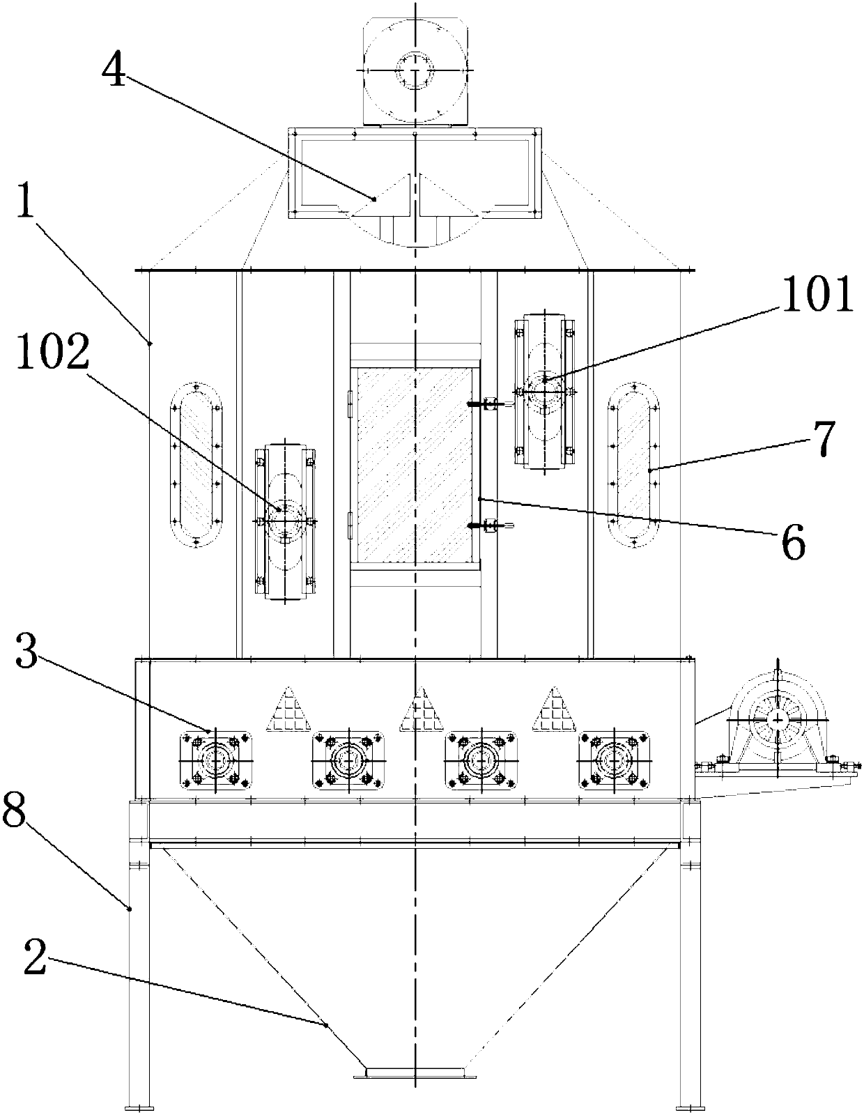
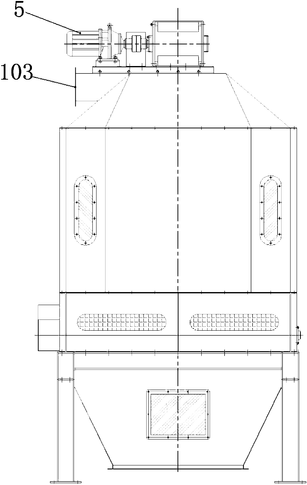
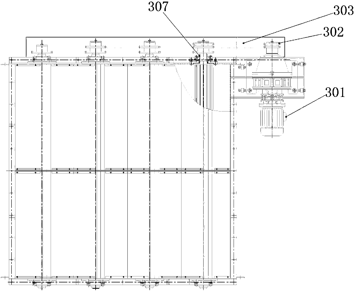
[0021] Such as figure 1 with figure 2 As shown, the present invention is realized in this way, the material cooler with uniform and controllable feeding includes a storage bin 1 and a lower hopper 2 located below the storage bin 1, and its structural feature is that the storage bin 1 and the lower An impeller feeding device 3 for controlling feeding is installed between the hoppers 2; on the one hand, the present invention simplifies the structure of the material cooler to make the structure more compact; , the material conveying efficiency can be adjusted by setting the specifications of the impeller and controlling its working speed, and the material conveying volume can be counted according to the rotation of the impeller to ensure that the material enters the lower hopper 2 from the storage bin 1 in an orderly and controllable manner; ...


PUM


Abstract

A material cooler with a uniform and controllable discharging function comprises a storage bin and a discharge hopper positioned below the storage bin, wherein an impeller discharging device for controlling discharging is mounted between the storage bin and the discharge hopper; an upper level detector and a lower level detector which are used for detecting the material height are arranged in thestorage bin and are electrically connected with a discharging controller; the discharging controller is in control connection with a driving part of the impeller discharging device; the impeller discharging device comprises a driving motor and an impeller component in driven connection with the driving motor through a transmission component; and the driving motor is electrically connected with thedischarging controller. According to the material cooler, the material conveying efficiency can be adjusted through setting the specification of impellers and controlling the operating speeds of theimpellers, the material conveying quantity is counted according to rotation of the impellers, so that a material can be orderly discharged in a controllable manner; quantization and ordered control ofdischarging are realized by use of the impellers; and meanwhile, through optimal design of the structure of the material cooler, the material cooling uniformity is improved, and material accumulationand leakage are prevented.

Description

technical field [0001] The invention relates to a material cooler, in particular to a material cooler with uniform and controllable feeding. Background technique [0002] In the feed processing and pelletizing section, the temperature of the feed is high after drying, and it needs to be cooled before packing. Therefore, a material cooler is required to ensure the uniformity of feed cooling during feed processing. [0003] The existing material cooler generally includes a storage bin with a cooling temperature control system and a lower hopper. Its typical structure is such as the pellet feed cooler disclosed in Chinese patent ZL201510421917.3. It includes an upper box and a lower box. By setting The cooling pipe between the upper box and the lower box forms a thermal cycle system, and then controls the temperature of the material in the box; however, this simple non-contact physical cooling not only has low temperature control efficiency, but also easily causes material cool...

Claims


Application Information

Patent Timeline
IPC IPC(8): B65G65/48A23N17/00
CPCA23N17/00B65G65/4881B65G2201/042
Inventor 王国荣谢家荣
Owner 广州天地实业有限公司
Learn More