Follow-up profile and follow-up support for wheelchair and follow-up mechanism

A follow-up mechanism and wheelchair vehicle technology, applied in the field of wheelchair vehicles, can solve the problems of heavy weight and large volume, and achieve the effects of fast electrical connection and disassembly, reduced machining amount, and convenient disassembly and assembly

Active Publication Date: 2018-03-23
NANJING KANGNI MECHANICAL & ELECTRICAL
View PDF11 Cites 1 Cited by
  • Summary
  • Abstract
  • Description
  • Claims
  • Application Information

AI Technical Summary

Problems solved by technology

Most of the existing improvements for wheelchairs are to increase its auxiliary functions, such as self-balancing function, seat swing function, rotation function, etc., but each function increase needs to increase the corresponding functional parts to make the volume and weight of the wheelchair Increase, if it is necessary to develop a wheelchair with multiple functions, it is difficult to solve the defects of large volume and excessive weight after the assembly of various functional parts

Method used


Image

  • Follow-up profile and follow-up support for wheelchair and follow-up mechanism
  • Follow-up profile and follow-up support for wheelchair and follow-up mechanism
  • Follow-up profile and follow-up support for wheelchair and follow-up mechanism

Examples


Embodiment 1

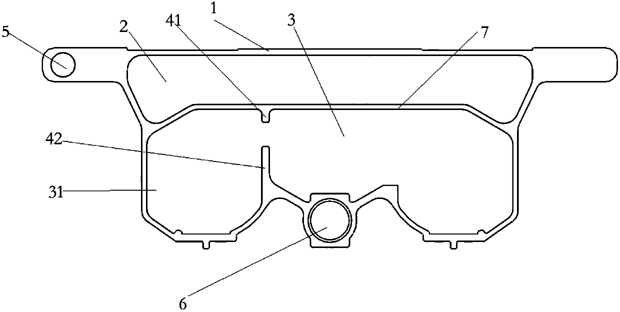
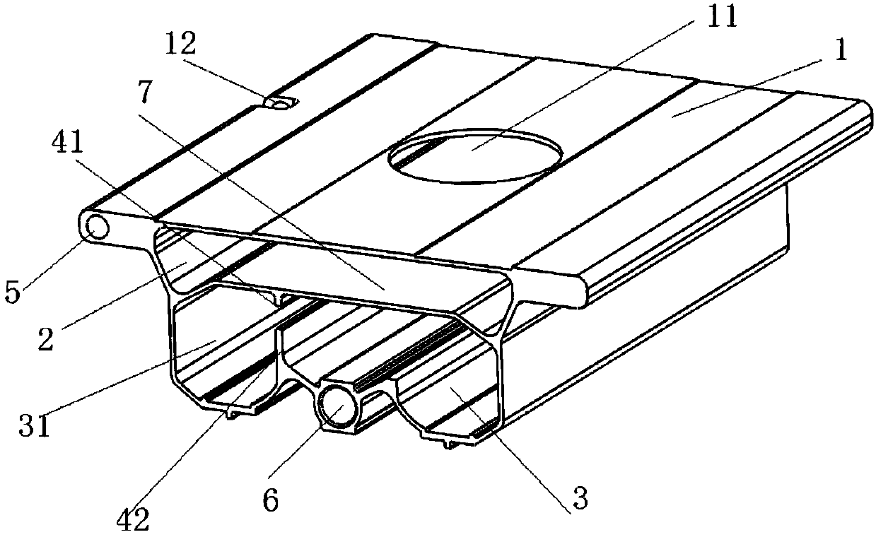
[0054] Such as figure 1 As shown, the follower profile of the present invention includes an upper end plate 1 arranged along the length direction of the profile, an accommodating cavity arranged below the upper end plate 1 , a positioning rib plate 7 , a guide rib, a connecting shaft hole 5 and a swinging shaft hole 6 . The positioning rib plate 7 has at least a positioning plane parallel to the upper end plate 1, and divides the interior of the accommodation cavity into an upper accommodation cavity 2 and a lower accommodation cavity 3 distributed up and down. At least one group of guide ribs is arranged on one side of the lower accommodation cavity 3, separating A side housing cavity 31 is used for placing the motor. A group of guide ribs is composed of upper guide ribs 41 and lower guide ribs 42 arranged side by side and spaced from each other, and extend from the lower end surface of the positioning rib plate 7 and the corresponding cavity wall surface of the lower accommo...

Embodiment 2

[0060] Such as Figure 6 As shown, the follower profile of the present invention includes an upper end plate 1 arranged along the length direction of the profile, an accommodation cavity arranged below the upper end plate 1, a positioning rib plate 7, a guide rib, a connecting shaft hole 5, a forming hole 22 and a swing shaft hole 6 . The positioning rib plate 7 has at least a positioning plane parallel to the upper end plate 1, and divides the interior of the accommodation chamber into an upper accommodation chamber 2 and a lower accommodation chamber 3 distributed up and down. Two groups of guide ribs 4 are arranged on both sides of the lower accommodation chamber 3, separating the There are two side accommodation cavities 31 and the middle cavity, and one of the side accommodation cavities 31 is used to place the motor. The middle cavity of the lower accommodation cavity 31 is provided with a horizontal reinforcing rib plate 35 along the length direction, which divides the...


PUM


Abstract

The invention discloses a follow-up profile and a follow-up support for a wheelchair and a follow-up mechanism. The follow-up profile comprises an upper end plate arranged in the length direction of the profile, a containing cavity formed in the lower portion of the upper end plate, a positioning rib plate, guide ribs, a connecting shaft hole and an oscillating shaft hole; the positioning rib plate is at least provided with a positioning plane parallel to the upper end plate and divides the containing cavity into an upper containing cavity and a lower containing cavity which are distributed upand down, at least one group of guide ribs are arranged on one side of the lower containing cavity, and a side containing cavity is separated out; one group of guide ribs are arranged in parallel from top to bottom and composed of upper guide ribs and lower guide ribs which have spacing between each other and extend out from the lower end face of the positioning rib plate and corresponding cavitywall surface of the containing cavity; the connecting shaft hole is formed in one side of the upper containing cavity; the swing shaft hole is formed in the lower end of the containing cavity. The follow-up support and the follow-up mechanism adopt intercepted follow-up profile equipment. According to the follow-up profile, an electric rotating mechanism and a swing mechanism are arranged simultaneously.

Description

technical field [0001] The invention relates to a wheelchair, in particular to a follow-up device for the wheelchair. Background technique [0002] As a means of transportation for the physically disabled and the elderly, wheelchairs bring certain convenience. Ordinary wheelchairs are generally composed of two parts: an upper seat and a lower chassis with a walking function. Most of the existing improvements for wheelchairs are to increase its auxiliary functions, such as self-balancing function, seat swing function, rotation function, etc., but each function increase needs to increase the corresponding functional parts to make the volume and weight of the wheelchair Addition, if it is necessary to develop a multifunctional wheelchair, it is difficult to solve the defects of large volume and excessive weight after the assembly of various functional components. Contents of the invention [0003] The object of the present invention is to solve the defects in the prior art,...

Claims


Application Information

Patent Timeline
Patent Type & Authority Applications(China)
IPC IPC(8): A61G5/10
CPCA61G5/1056A61G5/1072A61G5/1075
Inventor 尹琨李鹏柯旭费凯成徐荣叶华雷
Owner NANJING KANGNI MECHANICAL & ELECTRICAL
Why Eureka
Try Eureka