
Pose measurement and load sensing device for unmanned earth moving machine

A technology of pose measurement and load perception, applied in the direction of earth mover/shovel, construction, etc.

Inactive Publication Date: 2018-03-20
ARMY ENG UNIV OF PLA
View PDF4 Cites 6 Cited by
  • Summary
  • Abstract
  • Description
  • Claims
  • Application Information

AI Technical Summary

Problems solved by technology

However, several simple and clear characteristic indicators are rarely proposed to describe the load variation law of the interaction between the operation head and the operation target, so as to facilitate operation control.

Method used


Image

  • Pose measurement and load sensing device for unmanned earth moving machine
  • Pose measurement and load sensing device for unmanned earth moving machine
  • Pose measurement and load sensing device for unmanned earth moving machine

Examples


Embodiment 1

[0021] "A Pose Measurement and Load Sensing Device for Unmanned Operation Process of Earthmoving Machinery with Circular Saw Operating Head".

[0022] attached Figure 4 The utility model is an earth moving machine with a circular saw head. When this type of earthmoving machine is operated by remote control when there is no one on site, it is necessary to accurately adjust the circular saw of the working head to the target point and the appropriate working direction (for example, the working head of the circular saw needs to be perpendicular to the direction of the steel bar or along the existing Grooving direction), at the same time, it is necessary to control the feed speed or feed amount of the working head according to the load change law during the cutting process.

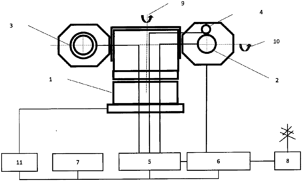
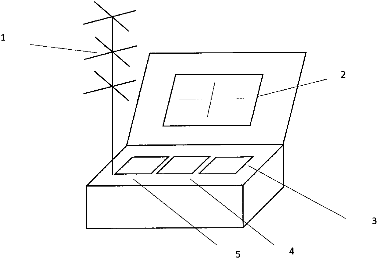
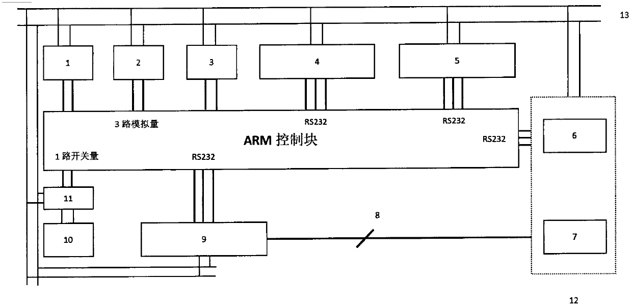
[0023] This embodiment needs to construct the airborne measurement sensing device (refer to the attached figure 1 , which is the core of the present invention) and the remote control end image transmission ...

Embodiment 2

[0031] This embodiment is "a device for pose measurement and load sensing in an unmanned operation process of an earth-moving machine with a hydraulic shearing head". This type of unmanned earthmoving machinery is mainly used for cutting steel bars and other goals in high-risk operations such as building demolition, emergency rescue, explosion protection, rescue and even military industry. It is necessary to accurately adjust the hydraulic shears of the working head to the target point and the appropriate working direction (such as the direction of the vertical steel bar), and at the same time, it is necessary to control the feed speed or feed rate of the hydraulic shears according to the law of load changes during the shearing process. The target pose measurement Especially important with load sensing.

[0032] This embodiment needs to construct the airborne measurement sensing device (refer to the attached figure 1 , which is the core of the present invention) and the remot...


PUM


Abstract

The invention relates to a pose measurement and load sensing device for a unmanned earth moving machine, and mainly solves the problems of operation target confirmation and pose measurement related tothe operation process of the unmanned earth moving machine and load change rule sensing in the working process of an operation head. The device comprises the structures and the contents of a high-precision holder, a focal distance-change and aperture-change camera, an illumination device, a laser distance measurement sensor, an embedded control amplifying module, a remote image and data transmission system, and a display screen with cross lines; oil pressure sensors mounted in an oil inlet of the mounting head and an oil outlet of a main pump are used for detecting pressure change rules; anda remote end operation hand is helped to realize precise and effective control of the feeding speed, the feeding quantity and the feeding direction of the operation head. The device has the followingadvantages: cheap, reliable and practical pose measurement and load sensing solutions and devices are provided for remote control of precise and effective operations.

Description

1. Technical field [0001] The invention relates to earth-moving machinery (construction machinery), especially unmanned earth-moving operation machinery 2. Background technology [0002] At present, earth moving machinery used for functions such as excavation, cutting, shearing, drilling, and crushing is widely used in construction, water conservancy construction, road construction, airport construction, mining, wharf construction, farmland improvement and other projects. With the continuous change of the working environment of earth-moving machinery, for example, earth-moving machinery often needs to be constructed in disaster sites such as earthquakes, floods, tsunamis, and harsh working conditions of high temperature, high cold, high altitude, and high radiation. Operators often have to risk their lives. Therefore, many manufacturers have begun to develop unmanned earthmoving machinery (earthmoving machinery with remote control or completely autonomous operation), such as...

Claims


Application Information

Patent Timeline
IPC IPC(8): E02F9/26E02F9/22
CPCE02F9/2221E02F9/264
Inventor 王新晴王东邵发明蒋成明殷勤马昭烨俞垚魏黄杰孟凡杰
Owner ARMY ENG UNIV OF PLA
Learn More